Digital Lookup Table with Don't Care in Input Definitions
The Digital Lookup Table with Don't Care in Input Definitions models combinatorial logic defined with a truth table. The truth table maps logical combinations of input states to output states. Unlike the Digital Lookup Table, this device allows the input space to include don't care inputs. A default output state determines the output if the input state is not defined in the table.
The Digital Lookup Table with Don't Care in Input Definitions is even more powerful than the Digital Lookup Table, especially for defining state machines or complex logic. Using the Lookup Table with don't care input definitions, you can easily implement, test, and revise extremely complex logic, all without changing the schematic view of the design.
If you do not require input definitions which include don't care states, see Digital Lookup Table. The points definition of the Digital Lookup Table is more flexible and it is slightly easier to configure.
In this topic:
| Model Name: | Digital Lookup Table with Don't Care in Input Definitions | |||
| Simulator: | This device is compatible with the SIMPLIS simulator. | |||
| Parts Selector Menu Location: | ||||
| Symbol Library: | None - the symbol is automatically generated when placed or edited. | |||
| Model Library: | None - the model is automatically generated when the simulation is run. | |||
| Subcircuit Names: |
|
|||
| Symbol: |
|
|||
| Multiple Selections: | Only one device at a time can be edited. | |||

Editing the Digital Lookup Table with Don't Care in Input Definitions
To configure the Digital Lookup Table with Don't Care in Input Definitions, follow these steps:
- Double click the symbol on the schematic to open the editing dialog to the Parameters tab.
- Make the appropriate changes to the fields described in the table below the image.
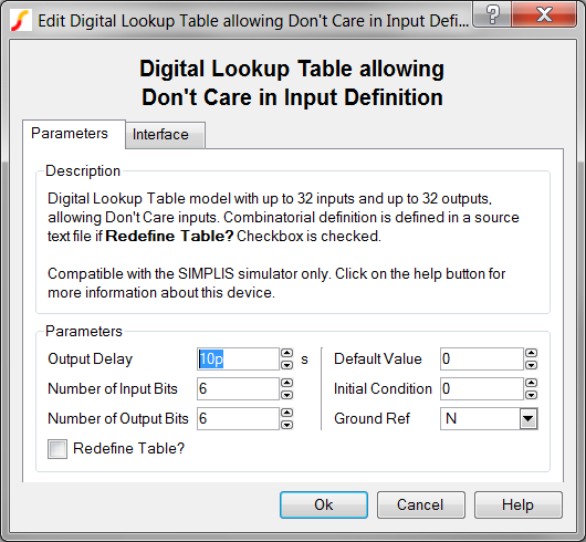
| Label | Parameter Description |
| Propagation Delay | Delay from when the input state changes until the output changes |
| Number of Bits A | Number of input bits to first multiplier input, the number of output bits will be Number of Bits A * Number of Bits B |
| Number of Bits B | Number of input bits to second multiplier input, the number of output bits will be Number of Bits A * Number of Bits B |
| Redefine Source? | Determines whether the
source is to be redefined after the dialog is closed.
|
| Default Value | Default value of lookup table output if the input value is not found in the lookup table. |
| Initial Condition | Initial condition of the Lookup Table output at time=0 |
| Ground Ref | Determines whether or not a device has a ground reference pin. Any digital component that has an input or output pin connected to an analog circuit node must have its Ground Ref pin connected to an analog node. This is usually the ground on the schematic. |
To define the parameters for the interface between this digital component and each analog component connected directly to an input or output pin, follow these steps:
- From the Edit Digital Lookup Table with Don't Care in Input Definitions dialog box, click on the Interface tab.
- Make the appropriate changes to the fields described in the table below the image.
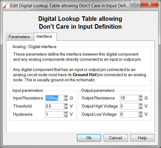
| Label | Parameter Description | |||||||
| Input Resistance | Input resistance of each Lookup Table input pin | |||||||
| Hysteresis, Threshold | 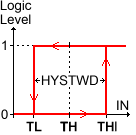 |
Hysteresis and
Threshold of the inputs. The hysteretic-window width, HYSTWD
is centered around Threshold (TH) voltage. To
determine the actual threshold ( TL , THI ),
substitute Threshold (TH) and Hysteresis
(HYSTWD) in each of the following formulas:
|
||||||
| Output Resistance | Output resistance of each Lookup Table output pin | |||||||
| Output High Voltage | Output high voltage for each Lookup Table output pin | |||||||
| Output Low Voltage | Output low voltage for each Lookup Table output pin | |||||||
Table Definition
You define the Digital Lookup Table with Don't Care in Input Definitions with an ASCII text file. Unlike the Digital Lookup Table, this device requires a single column to define each input and output bit. The points definition file is otherwise similar to the definition of a regular Digital Lookup Table.
The input file is whitespace delimited, with spaces or tabs, or a combination of the two. Each line in the definition file defines the input states which correspond to a set of output states. The delimited line has three components - the input definitions, the delimiter (space or tab) which separates the input definitions from the output definitions, and the output definitions.
A points definition file example can be downloaded here: state_machine_lookup_table. This file is also included in the following zip archive: simplis_042_lut_dont_care_example.zip.
Input Definitions
Each line starts with the input definitions, starting with the most significant bit (MSB). Each bit in the input space is defined with one of three characters:
- 0 The input bit is required to be logic low for this input combination to test true.
- 1 The input bit is required to be logic high for this input combination to test true.
- - The input bit can be either logic low or logic high for this input combination to test true. Note: This don't care state is different than an unknown (x) state. As with any SIMPLIS logic, any unknown input state propagates to the output, creating a chain reaction of unknown states.
Input-to-Output Delimiter
The pipe character | must occur on every line after the input definitions and before the output definitions. As with all entries on the line, the pipe character should be separated by a space or tab character.
Output Definitions
After the input bits and the pipe delimiter, the outputs are defined starting with the MSB. Each output bit is defined with one of three characters:
- 0 The output bit is low for this input combination.
- 1 The output bit is high for this input combination.
- x The output bit is in the unknown state for this input combination. The "x" character is case-insensitive.
Examples
The test circuit used to generate the waveform examples in the next section can be downloaded here: simplis_042_lut_dont_care_example.zip.
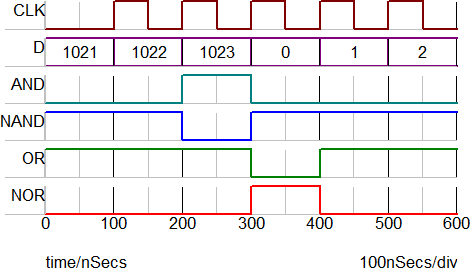
Waveforms
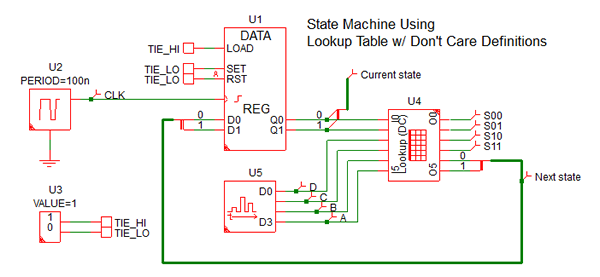
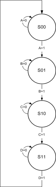
This example uses a Digital Lookup Table with Don't Care in Input Definitions and a digital register to implement a simple state machine. The state machine has four states (S00 through S03), four inputs (A, B, C, and D) and four state indication outputs. The definition of the state machine is described graphically in the following state transition diagram.
| State Diagram | Lookup Table Definition | |||||||||||||||||||||||||||||||||||||||||||||||||||||||||||||||||||||||||||||||||||||||||||||||||||||||||||||||||||||||||||||||||||||||||||||||
|
|
|||||||||||||||||||||||||||||||||||||||||||||||||||||||||||||||||||||||||||||||||||||||||||||||||||||||||||||||||||||||||||||||||||||||||||||||
In this example, the initial state is S00. The state machine transitions to the next state only on a rising clock edge when the A input is high. These conditions are met at time=0.5us. Shortly after the state machine moves to the S01 state, the A, C, and D inputs transition high for a clock cycle to test that the machine will not change state erroneously. The cycle repeats every 1us with the state machine transitioning through all four states.
Subcircuit Parameters
Because the Digital Lookup Table with Don't Care in Input Definitions model is generated by a template script when the simulation is executed, a hand-coded model cannot be inserted into a netlist. The template script for this device is simplis_make_signal_source_model.sxscr, which licensed users can download as part of a zip archive of all built-in scripts.
To download the zip archive, follow these steps:
- Click http://www.simetrix.co.uk/simetrix80/scripts.zip to download the script archive.
- Enter the user name and password you received with your license file.
The following parameter table defines the parameters used in this model.
| Parameter Name | Label | Data Type | Range | Units | Parameter Description | |||||||
| DEFAULT | Default Value | Number | none | Default value of lookup table output if the input value is not found in the lookup table. | ||||||||
| GNDREF | Ground Ref | String |
|
none | Determines whether or not a device has a ground reference pin. Any digital component that has an input or output pin connected to an analog circuit node must have its Ground Ref pin connected to an analog node. This is usually the ground on the schematic. | |||||||
| HYSTWD, TH |
Hysteresis, Threshold |
Number | min: 1f | V | |
Hysteresis and Threshold of
the inputs. The hysteretic-window width, HYSTWD is centered around
Threshold (TH) voltage. To determine the actual threshold (
TL , THI ), substitute Threshold (TH) and
Hysteresis (HYSTWD) in each of the following formulas:
|
||||||
| IC | Initial Condition | Number |
|
none | Initial condition of the Lookup Table output at time=0 | |||||||
| NUMBITS_A | Number of Bits A | Integer | none | Number of input bits to first multiplier input, the number of output bits will be Number of Bits A * Number of Bits B | ||||||||
| NUMBITS_B | Number of Bits B | Integer | none | Number of input bits to second multiplier input, the number of output bits will be Number of Bits A * Number of Bits B | ||||||||
| OUT_DELAY | Propagation Delay | Number | 1f to 1024 | s | Delay from when the input state changes until the output changes | |||||||
| REDEFINE_SOURCE | Redefine Source? | Boolean | none | Determines whether the source
is to be redefined after the dialog is closed.
|
||||||||
| RIN | Input Resistance | Number | min: 100 | Ω | Input resistance of each Lookup Table input pin | |||||||
| ROUT | Output Resistance | Number | min: 1m | Ω | Output resistance of each Lookup Table output pin | |||||||
| VOH | Output High Voltage | Number | any | V | Output high voltage for each Lookup Table output pin | |||||||
| VOL | Output Low Voltage | Number | any | V | Output low voltage for each Lookup Table output pin | |||||||
Common File Formatting Issues
-
An input file without an extra empty line after the last point definition:
If you examine the file example, it contains 6 lines: 4 are comments, one is an input definition, and the last one is an empty line. This empty line MUST be present at the end of each definition files. If the line is not present, the following error occurs:
*** ERRORS REPORTED BY SIMPLIS ***
****************************************
 <<<<<<<< Error Message ID: 1179 >>>>>>>>

 points file AND_NA~1.TXT

 No data point has been defined in this file.
 This model requires 1 data points to be defined.

*** END SIMPLIS ERROR REPORT ***
-
An input file that contains non-ASCII characters:
A points file that contains non-ASCII characters cannot be read by SIMetrix/SIMPLIS; as a result, the Lookup Table creation is aborted and the following errors are generated:
 Error : The file 'and_nand_points.txt' contained some non-ascii characters
 File read has been aborted

 *** ERRORS REPORTED BY SIMPLIS ***
 ****************************************
 <<<<<<<< Error Message ID: 1057 >>>>>>>>

input file file_path\SIMPLIS_Data/simplis_041_digitallookuptable_file_example.deck, line 76:
 + VOL=0 VOH=5 DEFAULT=2 OUT_DELAY=1e-011 NPTS=0 NUMBITS_OUT=2 NUMBITS_IN=10 FILE=AND_NA~1.TXT

 A positive integer to represent
 the value for `NPTS' is expected
 at the location where `0'
 occupies.

*** END SIMPLIS ERROR REPORT ***
-
Comments at the end of the point-definition line:
If you have a comment in a point-definition line, the following error occurs:
*** ERRORS REPORTED BY SIMPLIS ***
****************************************
 <<<<<<<< Error Message ID: 1179 >>>>>>>>

 points file AND_NA~1.TXT, line 5
     1023        0       1       *** illegal comment
                                 ^

 Unexpected entry `***' when end of line
 is expected while reading point #1.

*** END SIMPLIS ERROR REPORT ***