Tutorial 1 - A Simple Ready to Run Circuit
This tutorial demonstrates a basic simulation on a ready to run to circuit. All you need to do is load the circuit and press F9 to run it. We will then make a few changes to the circuit and make some extra plots.
This tutorial demonstrates the basic features without having to get into the details of setting up a simulation. Proceed as follows:
-
Select the menu and if not already select Schematic Files in the file type drop down box. Select the schematic file TUTORIAL1 which you should find in the folder EXAMPLES/SIMetrix/Tutorial (See Examples and Tutorials - Where are They?). Click on Open to open this file.
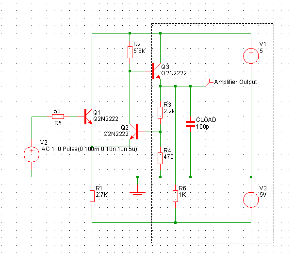
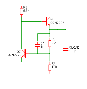
A schematic window will open with the following circuit:
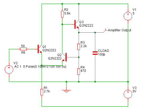 This is a simple feedback amplifier designed to amplify a 100mV pulse up to around 500mV. The basic requirement of the design is that the pulse shape should be preserved, DC precision is important but is not critical. The above is our first attempt at a design but has not yet been optimised.
This example circuit has been setup to be 'ready to run'.
This is a simple feedback amplifier designed to amplify a 100mV pulse up to around 500mV. The basic requirement of the design is that the pulse shape should be preserved, DC precision is important but is not critical. The above is our first attempt at a design but has not yet been optimised.
This example circuit has been setup to be 'ready to run'.
- To start the simulation, select from the schematic window or press F9. The simulation will not take long, on a modern machine less than half a second.
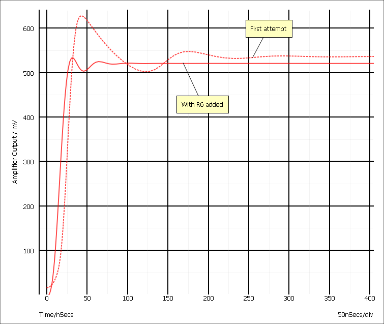
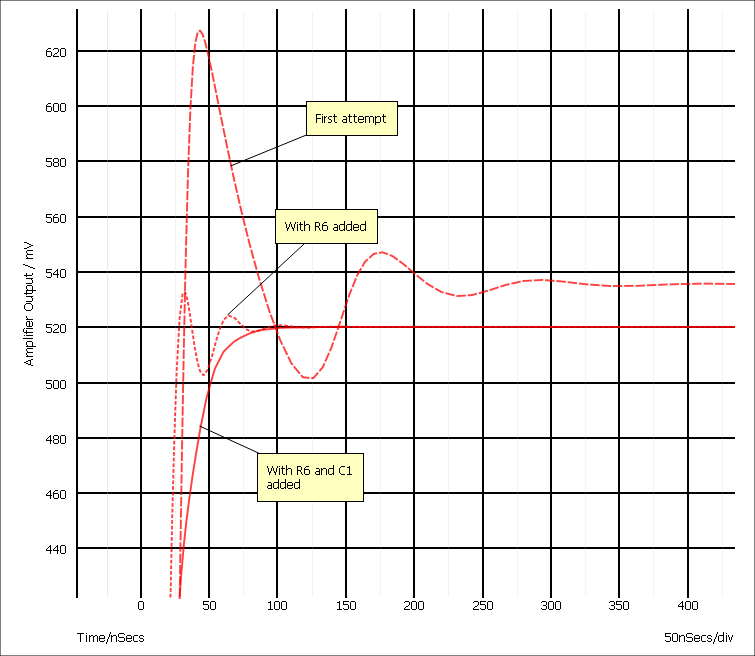
You will see a graph of the output voltage appear:
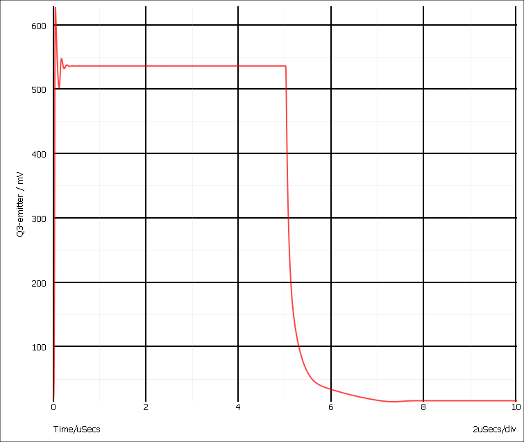
As can be seen, our amplifier doesn't work all that well. There are two problems.
- There is substantial ringing on the rising edge, probably caused by the capacitative load.
- The falling edge is somewhat sluggish.
 To make this modification, proceed as follows:
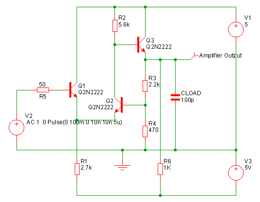
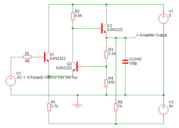
- Press the Resistor button in the parts toolbar. Alternatively, select the menu or, if you prefer, . A resistor symbol will appear. Place this in the location shown in the diagram above. Click the left mouse button to fix it to the schematic. You may now see another resistor symbol appear (depending on how the system options are set). Cancel this by clicking the right mouse button.
- Now wire up the resistor. There are a number of ways of doing this. If you have a three button mouse or wheel mouse, one way is to use the middle button (or wheel). Pressing it once will start a wire. Pressing it again will fix it and start a new one. Pressing the right button will terminate it. If enabled you can also use the 'smart-wiring' method. Just take the mouse pointer to the pin of the resistor. You will see a pen symbol appear as the mouse gets close to the pin. Left click then move the mouse cursor to the destination then left click again. This method will automatically locate a route for the wire if one exists. You can also enter wiring mode by selecting the toolbar wire button. This puts schematic into a permanent wiring mode where the left key is always used for wiring. Revert to normal mode by pressing the wire button again.
- Re run the simulation by pressing F9.
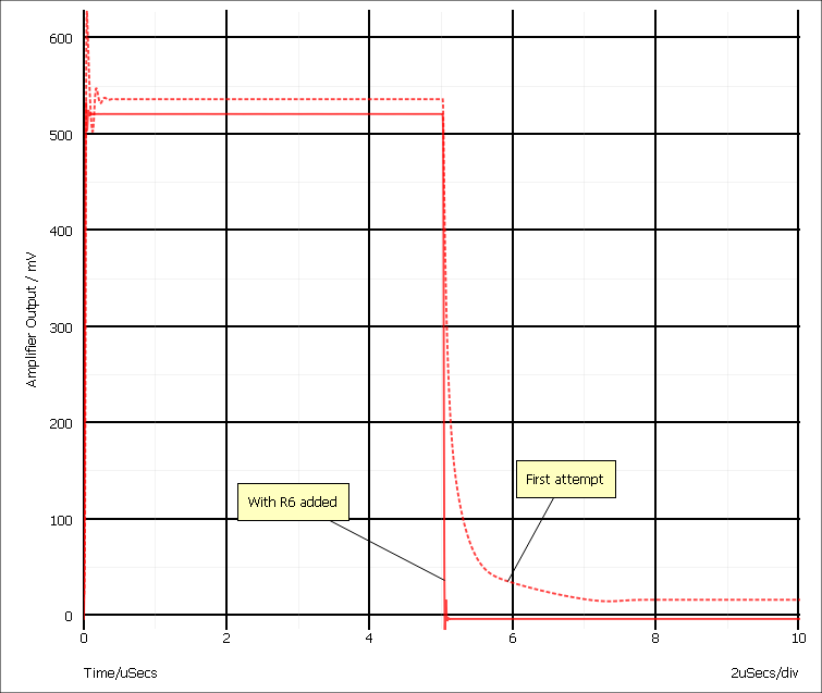
As you can see, The problem with the trailing edge has been fixed and the ringing is much improved.
Now let's have a look at the ringing in more detail. To do this, we need to zoom in the graph by adjusting the limits of the axes. There are two ways of doing this. The quickest is to simply drag the mouse over the region of interest. The other method is to manually enter the limits using the Edit Axis Dialog Box. To zoom with the mouse, proceed as follows:
- Make sure that the graph window is selected by clicking in its title bar.
- Place the cursor at the top left of the region of interest i.e to the left of the y-axis and above the top of the red curve.
- Press the left mouse key and while holding it down, drag the mouse to the bottom right of the area you wish to zoom in. You should see a rectangle appear as you drag the mouse.
- Release the mouse key. You should see something like:
 If you don't get it quite right, press the Undo Zoom button:
  to return to the previous view. You can also use the left, right, up and down arrow keys to shift the position of the curves.
We can probably improve the ringing by adding a small phase lead in the feed back loop. This can be done by connecting a small capacitor between the emitter of Q3 and the base of Q2. There isn't room to add this tidily at present, so first, we will move a few parts to make some space. Proceed as follows:
-
In the schematic window, drag the mouse with the left key pressed over the region shown by the dotted lines below:
 As you drag the mouse, a rectangle should appear.
-
Release the mouse. The area enclosed will turn blue:
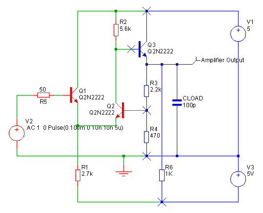 The blue wires and parts are said to be selected. To move them...
- Place the cursor within one of the selected parts - V1 say - then press and hold the left mouse key.
- Move the mouse to the right by two grid squares then release the left key.
-
Unselect by left clicking in an empty area of the schematic. This is what you should now have:
-
Wire in the capacitor C1 as shown below using a similar procedure as for the resistor R6.
-
Double click C1. You should see the following dialog box appear:
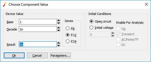 You can type the new value in directly in the Result box or you can select a value using the mouse alone with the up and down arrow buttons. Leave the Initial Conditions
setting at its default (Open Circuit)
You can type the new value in directly in the Result box or you can select a value using the mouse alone with the up and down arrow buttons. Leave the Initial Conditions
setting at its default (Open Circuit)
-
Now re-run the simulation. This is the result you should see:
You will notice that a new curve is displayed each time you run a new simulation. This is the default behaviour but this can be changed so that, for example, old curves are deleted leaving only the latest on view. To do this, double click the probe - that is the object labelled "Amplifier Output". Set History to 1 and close the box. (For more information see Probe Options Sheet). You can change the number of curves that are shown at any time using the popup menu .
We will now round off tutorial 1 by introducing AC analysis.
AC analysis performs a frequency sweep over a specified frequency range. To set one up, follow these instructions:
-
In the schematic window, select the menu . This is what you will see
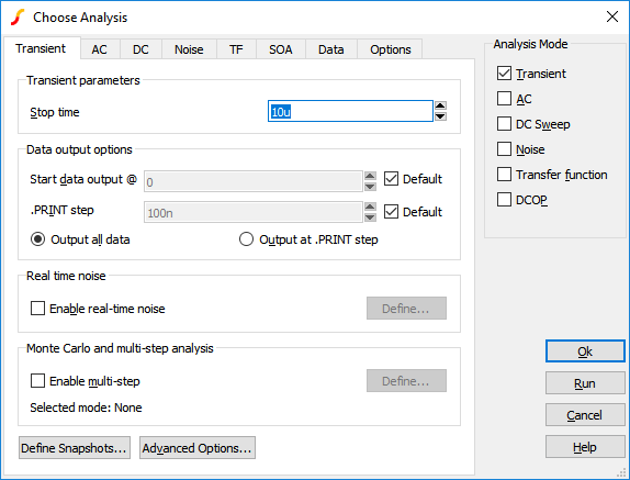 Click AC check box and uncheck the Transient check box. The details of the AC sweep have already been set up - click the AC tab at the top to see them.
- Run the simulation - this will open a new graph sheet.
| ◄ Introduction | Tutorial 2 - A Simple SMPS Circuit ▶ |