4.4 Virtual Winding Machine View
This section of the tutorial will introduce you to MDM's Virtual Winding Machine View, which draws a visual representation of how the windings should be wound onto the bobbin, to help you build your transformer in the real world.
In this topic:
Key Concepts
This topic addresses the following key concepts:
- MDM can draw a transformer winding diagram, showing on which bobbin pin to start winding a winding, how to distribute it along and around the bobbin, and which bobbin pin to finish on.
What You Will Learn
In this topic, you will learn the following:
- How to add create a winding diagram using the MDM Virtual Winding Machine View.
- How to add tape in between windings without adding tape in between each layer of a winding.
4.4.1 Showing the Virtual Winding Machine View
Close all of the MDM Results Windows and the MDM Status Window.
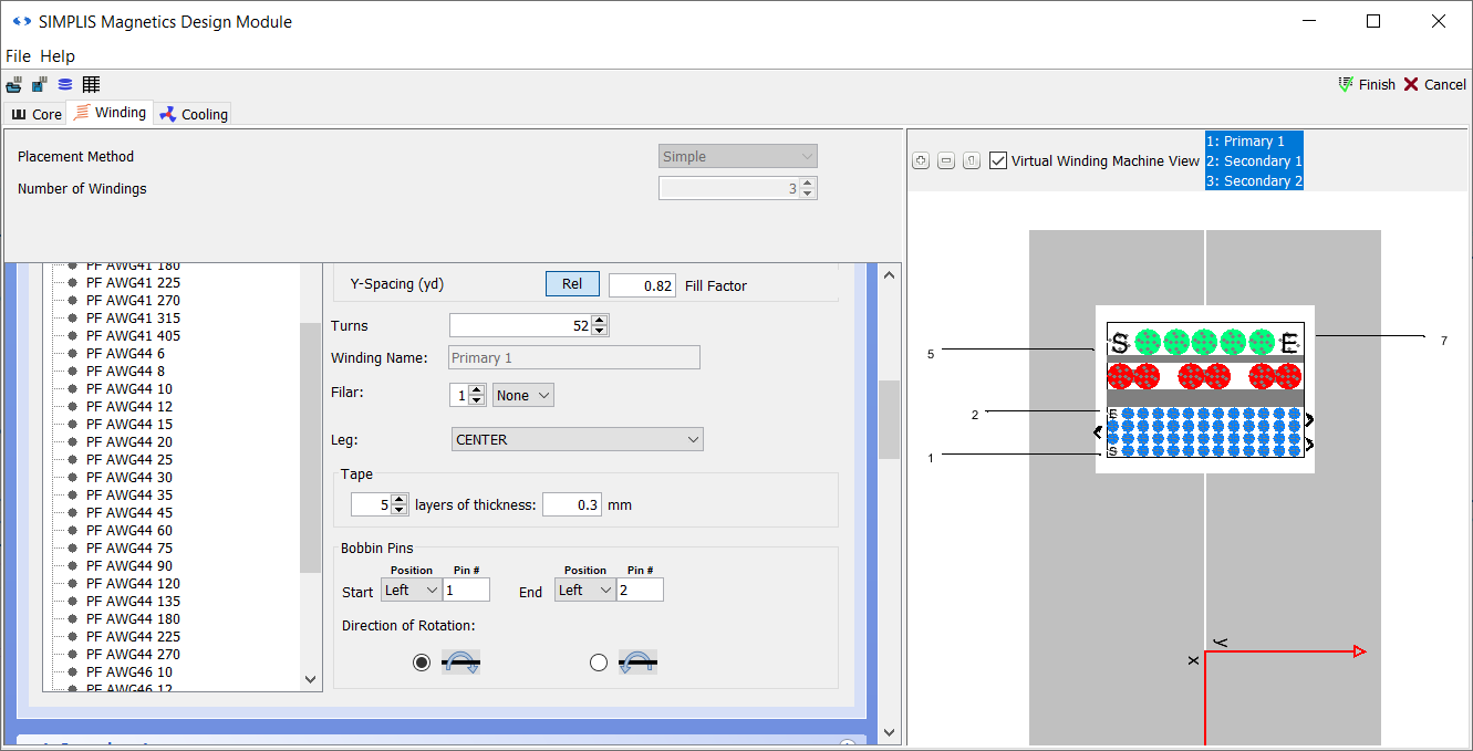
Double-click TX1, open the main MDM window by clicking Edit with SIMPLIS MDM... and then go the Winding tab.
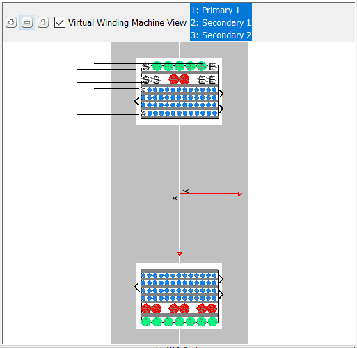
The visualization of the transformer has changed in several ways. First, it has been rotated by 90 degrees, because this is how you would typically look at a bobbin on a real winding machine. A lot of overlay has been added, as the Virtual Winding Machine View is being shown by default for all windings, which can be seen by observing that all winding names are selected in the field next to the Virtual Winding Machine View checkbox. To show only the Virtual Winding Machine View for the primary winding, click on 1: Primary 1, so that only it remains selected.
Zoom in to the top side of the core, to see better what the Virtual Winding Machine View is showing:
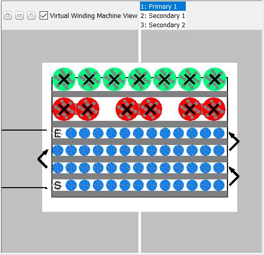
You can see that two turns are labeled S and E. This is where you start and end winding the wire, respectively. The arrows between layers show the direction of winding: starting from S, the wire is wound across the bobbin left to right, and when the end is reached, the next layer starts immediately and is wound back across the bobbin right to left, and so on.
An arrow points to S and away from E, but there is nothing at the end of the arrow. What should be there are bobbin pin numbers (labels).
4.4.2 Bobbin Pins
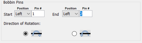
In the sub-panel for each winding to the left, you will see section called Bobbin Pins:
There are two pins to define, Start and End, which define the placement of the turns labeled S and E, respectively. By changing the option in the Position drop-down menu, you can pick whether the start or end pin is to the Left or the Right of the core. This is because some bobbins have pins on both sides of the core, while some bobbins only have pins to one side of the core. Under Pin # you enter the bobbin pin number or label.
Below this are radio buttons that determine the Direction of Rotation of the bobbin when this winding is being wound. The icons show how the bobbin rotates around
its axis in each case. For ![]() , imagine the lower winding window rotating out of the screen and the upper
winding window rotating into the screen, and conversely the reverse for
, imagine the lower winding window rotating out of the screen and the upper
winding window rotating into the screen, and conversely the reverse for ![]() .
.
To define the bobbin pins for each winding,
- For Primary 1, under Bobbin Pins, for Start leave the
Position as Left, and enter 1 for the Pin #. For
End also leave the Position as Left and enter 2 as the
Pin #. Leave the Direction of Rotation unchanged:
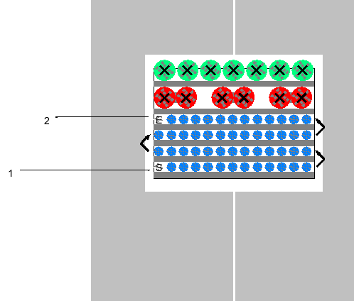
- Zoom out and move the visualization to be able to see the pin numbers:
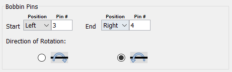
- For Secondary 1, under Bobbin Pins, for Start leave the
Position as Left, and enter 3 for the Pin #. For
End change the Position to Right and enter 4 as the
Pin #. Also change the Direction of Rotation to
 :
: 
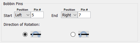
- For Secondary 2, under Bobbin Pins, for Start leave the
Position as Left, and enter 5 for the Pin #. For
End change the Position to Right and enter 7 as the
Pin # Leave the Direction of Rotation unchanged:
- To show the Virtual Winding Machine View for all three windings at once, hold the Ctrl
key and click on 2: Secondary 1 and 3: Secondary 2 in the box next to
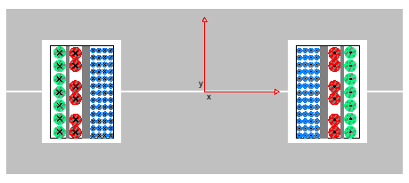
the Manufacturing View checkbox. Result: The visualization, when zoomed, should now look like this:
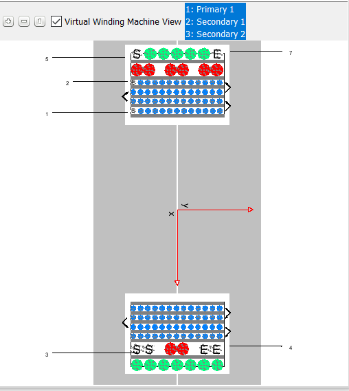
You can now see at which pin each winding starts and ends, and how it is wound along the bobbin. You can see that changing the Direction of Rotation for Secondary 2 caused its start and end turns to appear in the lower winding window. The direction of rotation changes on which side of the bobbin the wire begins and ends to be wound.
Assuming that you have correctly entered the pin numbers and pin locations for the bobbin you have selected for this transformer, you now have a complete picture showing how to wind the wires.
Feel free to experiment with different bobbin pin parameters to see how the visualization changes.
4.4.3 Adding Tape between Windings
So far in this tutorial, you have added tape by changing the X-Spacing parameter. You may have noticed that this adds tape in between each layer of a winding, as in this example with Primary 1. It is also possible to add tape only in between different windings, while placing no tape - no spacing - in between the layers of the same winding (and by extension, so set these two spacings - between layers and between windings - independently).
This is done via the Tape sub-panel which is located right above the Bobbin Pins sub-panel:
To add tape between Primary 1 and Secondary 1:
- Set the X-Spacing of Primary 1 to 0. Now there is no more tape between Primary 1 and the bobbin and in between the different layers of Primary 1.
- Set the X-Spacing of Secondary 1 also to 0. Now the tape which was previously visible between Primary 1 and Secondary 1 is also gone. As Secondary 1 is a single-layer winding, there is no tape between layers to remove.
- In the Tape sub-panel of Primary 1, use the spinner to set 5 layers of tape, and set the tape thickness to be 0.3.
Result: The Tape sub-panel, and the visualization, when zoomed, should now look like this:
Now there is tape, of total thickness 1.5mm, in betwen Primary 1 and Secondary 1, without any tape being present between the layers of Primary 1.
Note that the X-Spacing parameter not only adds space (i.e. tape) in between the layers of one winding, but also before that winding (if it is the first winding around the bobbin, between the bobbin and that winding, and for subsequent windings, between that winding and the previous one).
On the other hand, the Tape parameter adds space (i.e. tape) after a winding. It offsets the placement of the next winding - if it exists - regardless of that winding's X-Spacing parameter. For example, if you were to now add X-Spacing again for Secondary 1, the total space in between Primary 1 and Secondary 1 would be the sum of the Tape of Primary 1 and the X-Spacing of Secondary 1. You can also add tape to Secondary 2, and it would be displayed, regardless of the fact that there are no subsequent windings.
If you wish to simulate the effect of adding tape only in between the bobbin and the first multilayered winding, without adding any tape in between the layers, then simply add the thickness of this tape to the Bobbin Width (wb). By combining the use of all of these different parameters, you can precisely control the placement of each winding and layer.
Now uncheck the Virtual Winding Machine View checkbox to take another look at your modified transformer design:
Click Finish. The Virtual Winding Machine View parameters you have entered have been saved, and will be available when you re-open this transformer design.
-A complete schematic with the inductor design developed in this sub-section, is available as 4.4_SIMPLIS_MDM_selfoscillating_flyback_converter_with_virtual_winding_machine_view.sxsch in the zip archive of schematic files. The transformer design itself is available as 4.4_transformerP70_vwmv.gmd in the same archive.
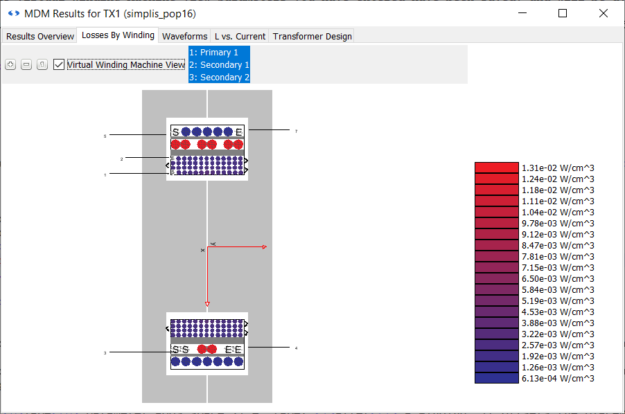
4.4.4 Viewing the Virtual Winding Machine View in the Results Window
The Virtual Winding Machine View can also be accessed in the Results Window after MDM post-processing is run:
- Press F9 to run the simulation.
- In the Results Window, go to the Losses by Winding tab.
- Check the Virtual Winding Machine View checkbox.
Result: The Bobbin Pin information you previously entered is now visible:
This completes the MDM tutorial. Please read through the final section, Conclusions.