SIMPLIS Device Types
In this topic:
Linear Resistors
The format for a linear resistor is:
Rname n+ n- valuewhere
| R | is the one-character element keyword "R" for linear resistors |
| name | is the individual name of the device |
| n+ | is the name of the positive node, and is a nonnegative integer |
| n- | is the name of the negative node, and is a nonnegative integer |
| value | is a floating-point number assigned as the value of the resistance (in ohms). This value can be positive, zero, or negative |
Linear Inductors and Capacitors
The formats for a linear inductor and a linear capacitor are:
Lname n+ n- value IC=init_cond
Cname n+ n- value IC=init_condwhere
| L | is the one-character element keyword "L" for linear inductors |
| C | is the one-character element keyword "C" for linear capacitor |
| name | is the individual name of the device |
| n+ | is the name of the positive node, and is a nonnegative integer |
| n- | is the name of the negative node, and is a nonnegative integer |
| value | is a floating-point number assigned as the value of the inductance (in henries) for an inductor or the value of the capacitance (in farads) for a capacitor. The value can be positive or negative, but not zero |
| IC= | is the three-character keyword "IC=" |
| init_cond | is a floating-point number assigned as the value of initial condition. It is the initial current (in amperes) for an inductor or the initial voltage (in volts) for a capacitor |
Independent Voltage and Current Sources
DC Sources
The formats for the dc sources are:
Vname n+ n- DC value
Iname n+ n- DC valuewhere
| V | is the one-character element keyword "V" for independent voltage sources |
| I | is the one-character element keyword "I" for independent current sources |
| name | is the individual name of the device |
| n+ | is the name of the positive node, and is a nonnegative integer |
| n- | is the name of the negative node, and is a nonnegative integer |
| DC | is the two-character keyword "DC" to signify that this is a DC source |
| value | is a floating-point number assigned as the source value. It is the voltage across the source element (in volts) for a dc voltage source or the current through the source (in amperes) for a dc current source |
Sawtooth Sources
The format for the independent sawtooth voltage source is:
Vname  n+  n-  SAW  V1=v1  V2=v2
+ FREQ=freq  DELAY=delay
+ OFF_UNTIL_DELAY={YES|NO}
+ IDLE_IN_POP=YES|NO
The format for the independent sawtooth current source is:
Iname  n+  n-  SAW  V1=v1  V2=v2
+ FREQ=freq   DELAY=delay
+ OFF_UNTIL_DELAY={YES|NO}
+ IDLE_IN_POP=YES|NO
where
| V | is the one-character element keyword "V" for independent voltage sources |
| I | is the one-character element keyword "I" for independent current sources |
| name | is the individual name of the device |
| n+ | is the name of the positive node, and is a nonnegative integer |
| n- | is the name of the negative node, and is a nonnegative integer |
| SAW | is the three-character keyword "SAW" to signify that this is a sawtooth source |
| V1= | is the three-character keyword "V1=" representing the source value at the start of a normal cycle |
| v1 | is a floating-point number assigned as the value of V1 (in volts) for a voltage source and the value of V1 (in amperes) for a current source |
| V2= | is the three-character keyword "V2=" representing the source value at the end of a normal cycle |
| v2 | is a floating-point number assigned as the value of V2 (in volts) for a voltage source and the value of V2 (in amperes) for a current source |
| FREQ= | is the five-character keyword "FREQ=" |
| freq | is a positive floating-point number assigned as the frequency of this source (in hertz) |
| DELAY= | is the six-character keyword "DELAY=" |
| delay | is a floating-point number assigned as the value of DELAY (in seconds) |
| OFF_UNTIL_DELAY= | is the sixteen-character keyword "OFF_UNTIL_DELAY=" |
| YES | is the three-character keyword "YES" |
| NO | is the two-character keyword "NO" |
| IDLE_IN_POP= | may have values YES or NO. Default is NO. If YES, the source will be inactive during POP and AC analyses. Inactive means that the source will hold its t=0 value throughout the analysis. If NO the source will behave normally during POP and AC analyses |
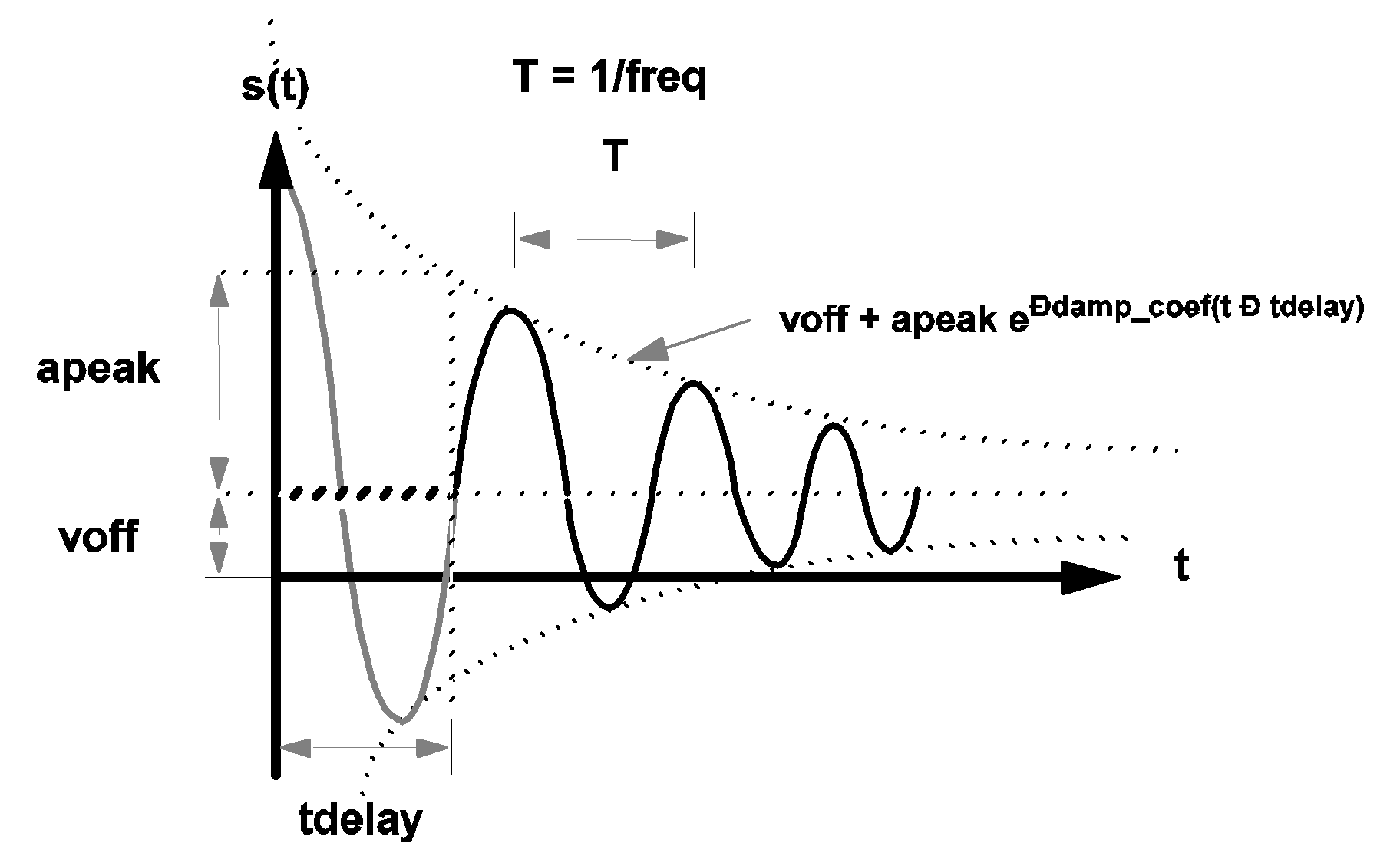
\[ s(t)=v1+[(v2-v1)(t-\textit{delay})]/T \] for ???MATH???\textit{delay} < t < (\textit{delay} +T)???MATH???
and:
\[ s(t)=s(t-T) \] for ???MATH???(\textit{delay} +T) < t???MATH???
where
| T=1/(freq) | is the period of the waveform |
\[ s(t) = s(t+T) \] for ???MATH???0 < t < \textit{delay}???MATH??? and OFF_UNTIL_DELAY=NO
and
\[ s(t)=v1 \] for ???MATH???0 < t < \textit{delay}???MATH??? and OFF_UNTIL_DELAY=YES
Whether the delay is positive or negative, the time-domain transient analysis performed by SIMPLIS always starts with the time variable set equal to 0.0.
The diagram below shows the waveforms of a sawtooth source. For t < delay and OFF_UNTIL_DELAY=YES, the waveform s(t) is shown in bold dashed line. For t < delay and OFF_UNTIL_DELAY=NO, the waveform s(t) is shown in heavy gray line.
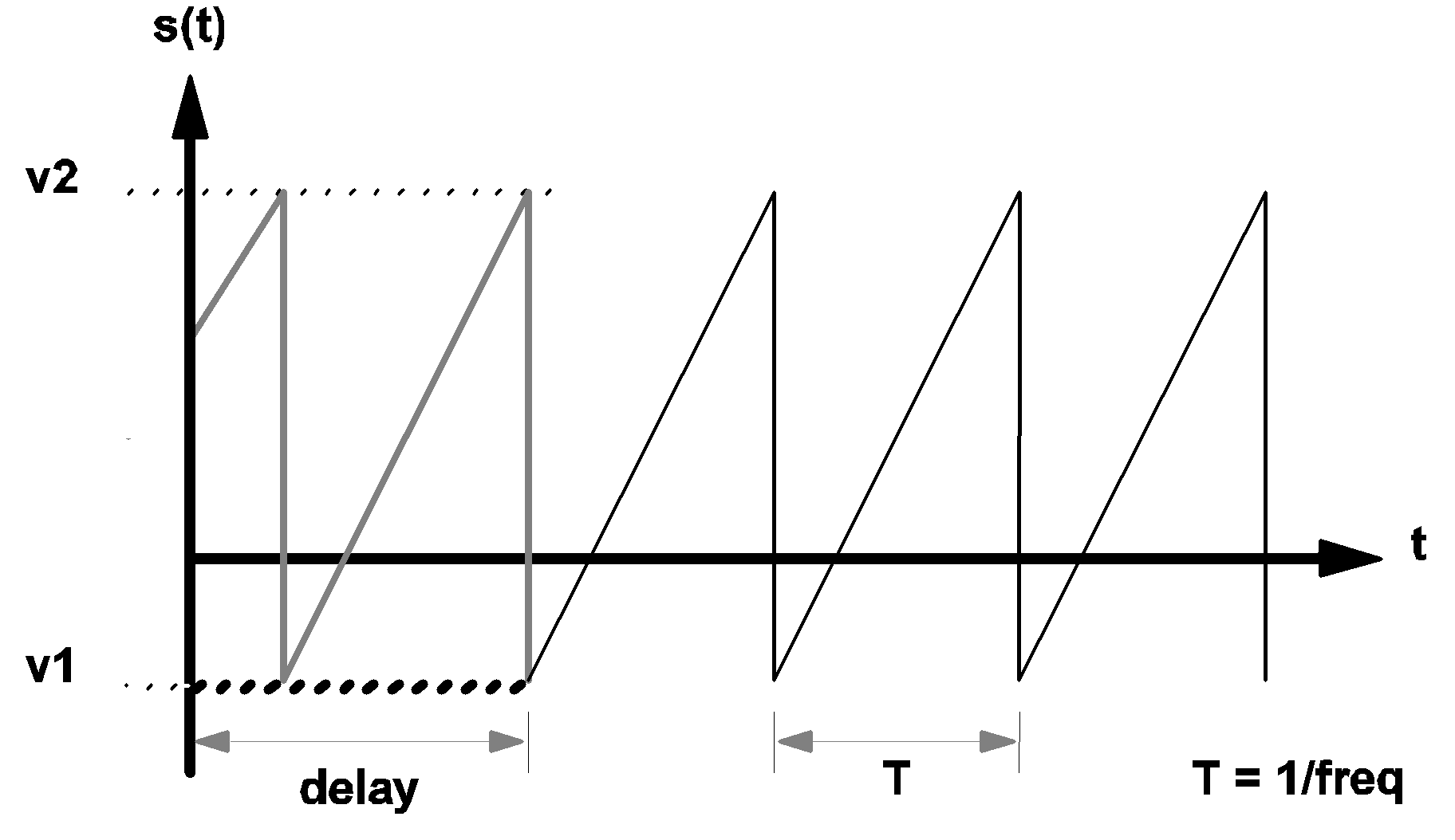 |
3.2 Waveform s(t) of a sawtooth source |
Triangular Sources
The formats for independent triangular voltage and current sources are:
Vname  n+  n-  TRI  V1=v1  V2=v2
+ FREQ=freq  DRATIO=dratio  DELAY=delay
+ OFF_UNTIL_DELAY={YES|NO} IDLE_IN_POP=YES|NO
and
Iname  n+  n-  TRI  V1=v1  V2=v2
+ FREQ=freq  DRATIO=dratio  DELAY=delay
+ OFF_UNTIL_DELAY={YES|NO} IDLE_IN_POP=YES|NO
where
| V | is the one-character element keyword "V" for independent voltage sources |
| I | is the one-character element keyword "I" for independent current sources |
| name | is the individual name of the device |
| n+ | is the name of the positive node, and is a nonnegative integer |
| n- | is the name of the negative node, and is a nonnegative integer |
| TRI | is the three-character keyword "TRI" to signify that this is a triangular source |
| V1= | is the three-character keyword "V1=" representing the source at the start of a normal cycle |
| v1 | is a floating-point number assigned as the value of V1 (in volts) for a voltage source or the value of V1 (in amperes) for a current source |
| V2= | is the three-character keyword "V2=" representing the source at the end of a normal cycle |
| v2 | is a floating-point number assigned as the value of V2 (in volts) for a voltage source or the value of V2 (in amperes) for a current source |
| FREQ= | is the five-character keyword "FREQ=" |
| freq | is a positive floating-point number assigned as the frequency of this source (in hertz) |
| DRATIO= | is the seven-character keyword "DRATIO=" |
| dratio | is a dimensionless floating-point number between 0.0 and 1.0, exclusively, assigned as the value of DRATIO |
| DELAY= | is the six-character keyword "DELAY=" |
| delay | is a floating-point number assigned as the value of DELAY (in seconds) |
| OFF_UNTIL_DELAY= | is the sixteen-character keyword "OFF_UNTIL_DELAY=" |
| YES | is the three-character keyword "YES" |
| NO | is the two-character keyword "NO" |
| IDLE_IN_POP= | may have values YES or NO. Default is NO. If YES, the source will be inactive during POP and AC analyses. Inactive means that the source will hold its t=0 value throughout the analysis. If NO the source will behave normally during POP and AC analyses |
\[ s(t)=v1+[(v2-v1)(t-\textit{delay})]/t1 \]
for delay < t < (delay + t1)
\[ s(t)=v2+[(v1-v2)(t-\textit{delay}-t1)]/(T-t1) \] for ???MATH???(\text{delay} + t1) < t < (\text{delay} + T)???MATH???
and
\[ s(t)=s(t-T) \] for ???MATH???(\textit{delay} + T) < t???MATH???
where
| T=1/(freq) | is defined as the period of the waveform |
| t1=DRATIO*T | is the duration in a period of the waveform where the source value is moving from the value of v1 to the value of v2. |
\[ s(t)=s(t+T) \] for ???MATH???0 < t < \textit{delay}???MATH??? and OFF_UNTIL_DELAY=NO
and
\[ s(t)=v1 for 0 < t < \textit{delay} \text{ and OFF_UNTIL_DELAY=YES.} \] Again, whether the delay is positive or negative, the time-domain transient analysis performed by the simulation always starts with the time variable set equal to 0.0. The diagram below shows the waveform, s(t), of a typical triangular source. For t < delay and OFF_UNTIL_DELAY=YES, the waveform s(t) is shown in bold dashed line. For t < delay and OFF_UNTIL_DELAY=NO, the waveform s(t) is shown in heavy gray line.
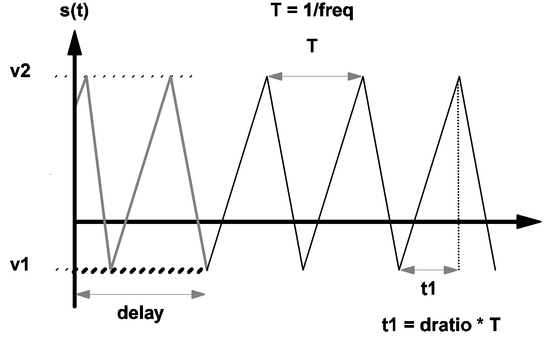 |
3.3 Waveform s(t) of a triangular source |
Square Wave Sources
The formats for independent square-wave voltage and current sources are:
Vname  n+  n-  SQU  V1=v1  V2=v2  FREQ=freq
+ DELAY=delay  OFF_UNTIL_DELAY={YES|NO}
+ [IDLE_IN_POP=YES|NO]
and
Iname  n+  n-  SQU  V1=v1  V2=v2  FREQ=freq
+ DELAY=delay  OFF_UNTIL_DELAY={YES|NO}
+ [IDLE_IN_POP=YES|NO]
where
| V | is the one-character element keyword "V" for independent voltage sources |
| I | is the one-character element keyword "I" for independent current sources |
| name | is the individual name of the device |
| n+ | is the name of the positive node, and is a nonnegative integer |
| n- | is the name of the negative node, and is a nonnegative integer |
| SQU | is the three-character keyword "SQU" to signify that this is a square source |
| V1= | is the three-character keyword "V1=" representing the source at the start of a normal cycle |
| v1 | is a floating-point number assigned as the value of V1 (in volts) for a voltage source and the value of V1 (in amperes) for a current source |
| V2= | is the three-character keyword "V2=" representing the source at the end of a normal cycle |
| v2 | is a floating-point number assigned as the value of V2 (in volts) for a voltage source and the value of V2 (in amperes) for a current source |
| FREQ= | is the five-character keyword "FREQ=" |
| freq | is a positive floating-point number assigned as the frequency of this source (in hertz) |
| DELAY= | is the six-character keyword "DELAY=" |
| delay | is a floating-point number expressing DELAY (in seconds) |
| OFF_UNTIL_DELAY= | is the sixteen-character keyword "OFF_UNTIL_DELAY=" |
| YES | is the three-character keyword "YES" |
| NO | is the two-character keyword "NO" |
| IDLE_IN_POP= | may have values YES or NO. Default is NO. If YES, the source will be inactive during POP and AC analyses. Inactive means that the source will hold its t=0 value throughout the analysis. If NO the source will behave normally during POP and AC analyses |
| ???MATH???s(t)=v2???MATH??? | for ???MATH???\textit{delay} < t < (\textit{delay} + T/2)???MATH???: |
| ???MATH???s(t)=v1???MATH??? | for ???MATH???(\textit{delay} + T/2) < t < (\textit{delay} + T)???MATH???: |
| ???MATH???s(t)=s(t-T)???MATH??? | for ???MATH???(\textit{delay} + T) < t???MATH???: |
The source function s(t) for ???MATH???t < \textit{delay}???MATH??? is defined as follows
| ???MATH???s(t)=s(t+T)???MATH??? | for ???MATH???0 < t < \textit{delay}???MATH??? and OFF_UNTIL_DELAY=NO |
| ???MATH???s(t)=v1???MATH??? | for ???MATH???0 <t < \textit{delay}???MATH??? and OFF_UNTIL_DELAY=YES |
where
| T=1/freq | T is defined as the period of the waveform |
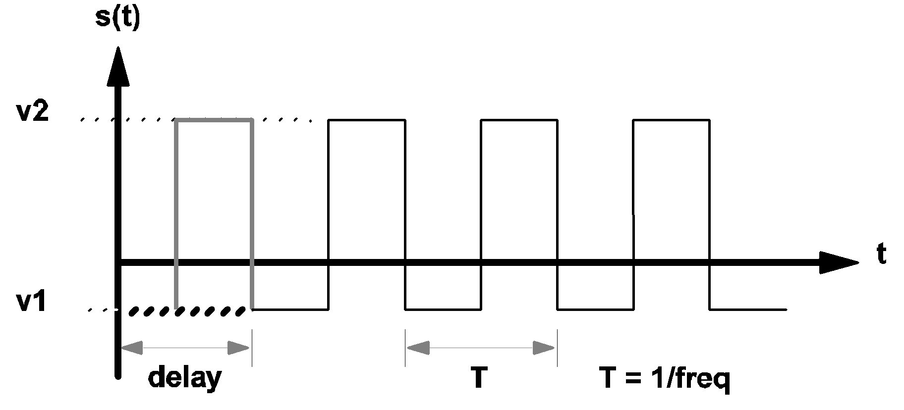 |
3.4 Waveform s(t) of a square wave source |
Pulse Sources with Zero Rise and Fall Times
The formats for the independent rectangular pulse sources are
Vname  n+  n-  PUL  V1=v1  V2=v2  FREQ=freq
+ DRATIO=dratio  DELAY=delay
+ OFF_UNTIL_DELAY={YES|NO}
+ [IDLE_IN_POP=YES|NO]
and
Iname  n+  n-  PUL  V1=v1  V2=v2 F REQ=freq
+ DRATIO=dratio  DELAY=delay
+ OFF_UNTIL_DELAY={YES|NO}
+ [IDLE_IN_POP=YES|NO]
| V | is the one-character element keyword "V" for independent voltage sources |
| I | is the one-character element keyword "I" for independent current sources |
| name | is the individual name of the device |
| n+ | is the name of the positive node, and is a nonnegative integer |
| n- | is the name of the negative node, and is a nonnegative integer |
| PUL | is the three-character keyword "PUL" to signify that this is a rectangular pulse source |
| V1= | is the three-character keyword "V1=" representing the source at the start of a normal cycle |
| v1 | is a floating-point number assigned as the value of V1 (in volts) for a voltage source and the value of V1 (in amperes) for a current source |
| V2= | is the three-character keyword "V2=" representing the source at the end of a normal cycle |
| v2 | is a floating-point number assigned as the value of V2 (in volts) for a voltage source and the value of V2 (in amperes) for a current source |
| FREQ= | is the five-character keyword "FREQ=" |
| freq | is a positive floating-point number assigned as the frequency of this source (in hertz) |
| DRATIO= | is the seven-character keyword "DRATIO=" |
| dratio | is a dimensionless floating-point number between 0.0 and 1.0, exclusively, assigned as the value of DRATIO |
| DELAY= | is the six-character keyword "DELAY=" |
| delay | is a floating-point number assigned as the value of DELAY (in seconds) |
| OFF_UNTIL_DELAY= | is the sixteen-character keyword "OFF_UNTIL_DELAY=" |
| YES | is the three-character keyword "YES" |
| NO | is the two-character keyword "NO" |
| IDLE_IN_POP= | may have values YES or NO. Default is NO. If YES, the source will be inactive during POP and AC analyses. Inactive means that the source will hold its t=0 value throughout the analysis. If NO the source will behave normally during POP and AC analyses |
| ???MATH???s(t)=v2???MATH??? | for ???MATH???\textit{delay} < t < (\textit{delay} + t1)???MATH??? |
| ???MATH???s(t)=v1???MATH??? | for ???MATH???(\textit{delay} + t1) < t < (\textit{delay} + T)???MATH??? |
| ???MATH???s(t)=s(t-T)???MATH??? | for ???MATH???(\textit{delay} +T) < t???MATH??? |
| T=1/freq | T is defined as the period of the waveform |
| t1=DRATIO*T | t1 is the duration in a period of the waveform where the source value is equal to v2 |
The source function s(t) for t < delay is defined as follows:
| ???MATH???s(t)=s(t+T)???MATH??? | for ???MATH???0 < t < \textit{delay}???MATH??? and OFF_UNTIL_DELAY=NO |
| ???MATH???s(t)=v1???MATH??? | for ???MATH???0 < t < \textit{delay}???MATH??? and OFF_UNTIL_DELAY=YES |
The waveform s(t) of a typical rectangular pulse source is shown in the diagram below. For t < delay and OFF_UNTIL_DELAY=YES, the waveform s(t) is shown in bold dashed line. For t < delay and OFF_UNTIL_DELAY=NO, the waveform s(t) is shown in heavy gray line.
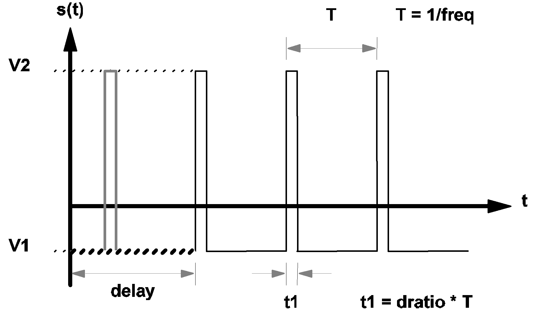 |
3.5 Waveform s(t) of a pulse-wave source |
Sinusoidal Sources
The formats for defining independent sinusoidal voltage and current sources are:
Vname  n+  n-  SIN  VOFFSET=voff  APEAK=apeak
+ FREQ=freq  {TDELAY=tdelay|PDELAY=pdelay}
+ OFF_UNTIL_DELAY={YES|NO} DAMP_COEF=damp_coef
+ [IDLE_IN_POP=YES|NO]
and
Iname  n+  n-  SIN VOFFSET=voff APEAK=apeak
+ FREQ=freq  {TDELAY=tdelay |PDELAY=pdelay}
+ OFF_UNTIL_DELAY={YES|NO} DAMP_COEF=damp_coef
+ [IDLE_IN_POP=YES|NO]
| V | is the one-character element keyword "V" for independent voltage sources |
| I | is the one-character element keyword "I" for independent current sources |
| name | is the individual name of the device |
| n+ | is the name of the positive node, and is a nonnegative integer |
| n- | is the name of the negative node, and is a nonnegative integer |
| SIN | is the three-character keyword "SIN" to signify that this is a sinusoidal source with possible damping |
| VOFFSET= | is the eight-character keyword "VOFFSET=" representing the DC offset of the source |
| voff | is a floating-point number assigned as the DC offset value (in volts) for a voltage source and the DC offset value (in amperes) for a current source |
| APEAK= | is the six-character keyword "APEAK=" representing the amplitude of the source at t = tdelay |
| apeak | is a nonnegative floating-point number assigned as volts for a voltage source and amperes for a current source |
| FREQ= | is the five-character keyword "FREQ=" representing the frequency of the source |
| freq | is a positive floating-point number assigned as the frequency of this source (in hertz) |
| TDELAY= | is the seven-character keyword "TDELAY=" representing the time delay of the source |
| tdelay | is a floating-point number assigned as the time delay (in seconds) |
| PDELAY= | is the seven-character keyword "PDELAY=" representing the phase delay of the source |
| pdelay | is a floating-point number assigned as the phase delay (in degrees). The specification of TDELAY and PDELAY are mutually exclusive |
| OFF_UNTIL_DELAY= | is the sixteen-character keyword "OFF_UNTIL_DELAY=" |
| YES | is the three-character keyword "YES" |
| NO | is the two-character keyword "NO" |
| IDLE_IN_POP= | may have values YES or NO. Default is NO. If YES, the source will be inactive during POP and AC analyses. Inactive means that the source will hold its t=0 value throughout the analysis. If NO the source will behave normally during POP and AC analyses |
| DAMP_COEF= | is the ten-character keyword "DAMP_COEF=" representing the damping coefficient of the source |
| damp_coef | is a floating-point number assigned as the damping coefficient (in 1/seconds) |
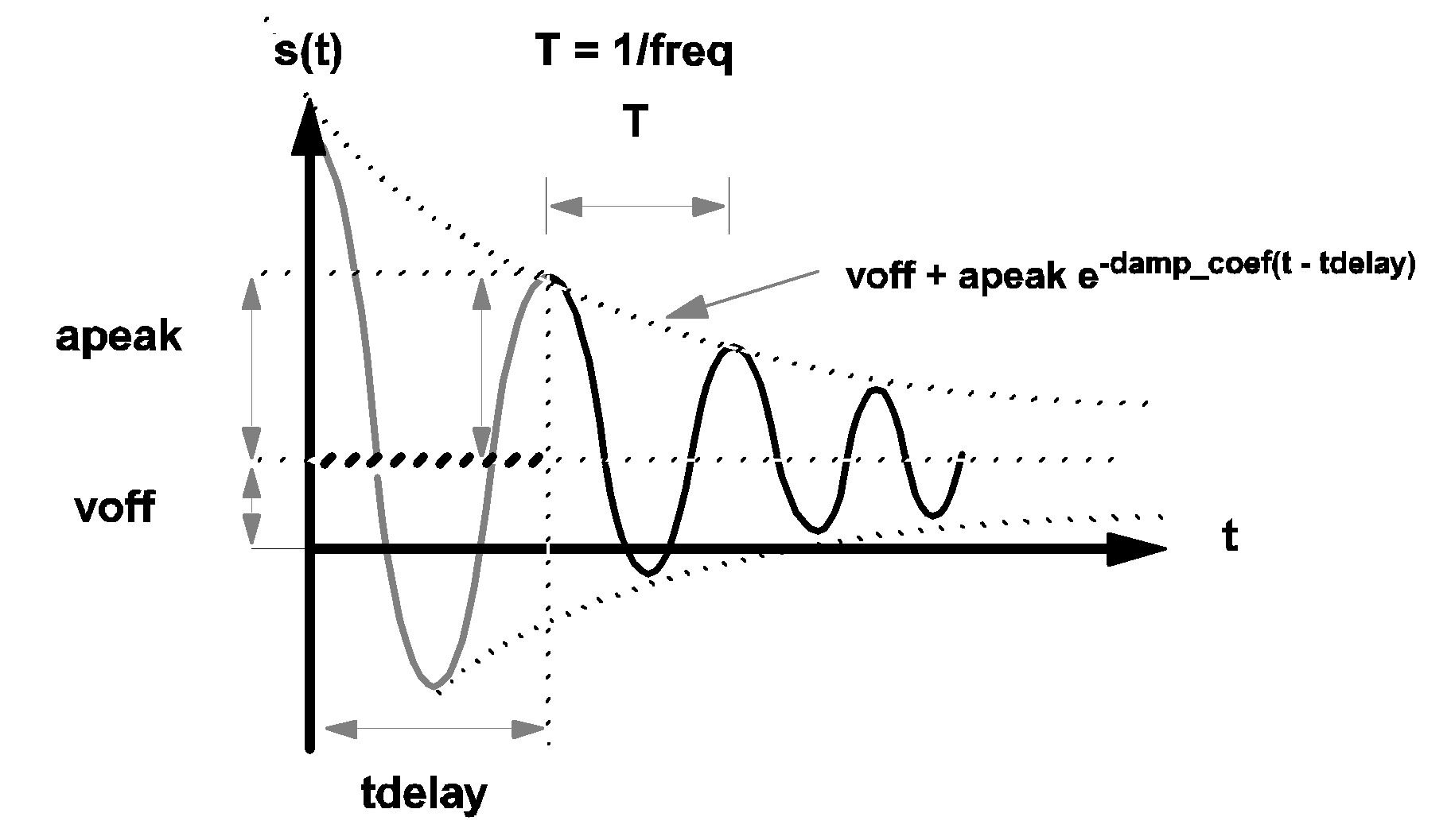
\[ s(t)=\textit{voff}+\textit{apeak}\cdot e^{-\textit{damp_coef}\cdot(t-\textit{tdelay})}\cdot\sin(2\cdot\pi\cdot\textit{freq}\cdot(t-\textit{tdelay})) \] The value of tdelay, computed from the value of pdelay (if pdelay is given), is:
\[ \textit{tdelay}=(\textit{pdelay})/(360*\textit{freq}). \]
If OFF_UNTIL_DELAY is assigned a value of YES, then the value of s(t) for t < tdelay is modified to:
| ???MATH???s(t)=voff???MATH??? | for ???MATH???t < \textit{tdelay}???MATH??? |
The waveform s(t) of a typical sinusoidal source is shown in the diagram below.
For t < delay and OFF_UNTIL_DELAY=YES, the waveform s(t) is shown in bold dashed line. For t < delay and OFF_UNTIL_DELAY=NO, the waveform s(t) is shown in heavy grey line.
 |
3.6 Waveform s(t) of a sinusoidal source |
Cosinusoidal Source
The formats for independent cosinusoidal voltage and current sources are:
Vname  n+  n-  COS  VOFFSET=voff  APEAK=apeak
+ FREQ=freq  {TDELAY=tdelay|PDELAY=pdelay}
+ OFF_UNTIL_DELAY={YES|NO}
+ DAMP_COEF=damp_coef
+ [IDLE_IN_POP=YES|NO]
and
Iname  n+  n-  COS  VOFFSET=voff  APEAK=apeak
+ FREQ=freq  {TDELAY=tdelay|PDELAY=pdelay}
+ OFF_UNTIL_DELAY={YES|NO}
+ DAMP_COEF=damp_coef
+ [IDLE_IN_POP=YES|NO]
where
| V | is the one-character element keyword "V" for independent voltage sources |
| I | is the one-character element keyword "I" for independent current sources |
| name | is the individual name of the device |
| n+ | is the name of the positive node, and is a nonnegative integer |
| n- | is the name of the negative node, and is a nonnegative integer |
| COS | is the three-character keyword "COS" to signify that this is a cosinusoidal source with possible damping |
| VOFFSET= | is the eight-character keyword "VOFFSET=" representing the DC offset of the source |
| voff | is a floating-point number assigned as the DC offset value (in volts) for a voltage source and the DC offset value (in amperes) for a current source |
| APEAK= | is the six-character keyword "APEAK=" representing the amplitude of the source at t = tdelay |
| apeak | is a nonnegative floating-point number assigned as the amplitude (in volts) for a voltage source and (in amperes) for a current source |
| FREQ= | is the five-character keyword "FREQ=" representing the frequency of this source |
| freq | is a positive floating-point number assigned as the frequency (in hertz) |
| TDELAY= | is the seven-character keyword "TDELAY=" representing the time delay of the source (use of TDELAY and PDELAY are mutually exclusive) |
| tdelay | is a floating-point number assigned as the time delay (in seconds) |
| PDELAY= | is the seven-character keyword "PDELAY=" representing the phase delay of the source (use of TDELAY and PDELAY are mutually exclusive) |
| pdelay | is a floating-point number assigned as the phase delay (in degrees) |
| OFF_UNTIL_DELAY= | is the sixteen-character keyword "OFF_UNTIL_DELAY=" |
| YES | is the three-character keyword "YES" |
| NO | is the two-character keyword "NO" |
| DAMP_COEF= | is the ten-character keyword "DAMP_COEF=" representing the damping coefficient of the source |
| damp_coef | is a floating-point number assigned as the damping coefficient (in 1/seconds) |
| IDLE_IN_POP= | may have values YES or NO. Default is NO. If YES, the source will be inactive during POP and AC analyses. Inactive means that the source will hold its t=0 value throughout the analysis. If NO the source will behave normally during POP and AC analyses |
\[ s(t)=\textit{voff}+\textit{apeak}\cdot e^{-\textit{damp_coef} \cdot (t - \textit{tdelay})}\cdot\cos(2\cdot\pi\cdot\textit{freq}\cdot(t-\textit{tdelay})). \] The value of tdelay, computed from the value of pdelay (if pdelay is given), is: \[ \textit{tdelay}=(\textit{pdelay})/(360*\textit{freq}) \]
If OFF_UNTIL_DELAY is assigned a value of YES, then the value of s(t) for t < tdelay is modified to
| ???MATH???s(t) = \textit{voff}???MATH??? | for ???MATH???t < \textit{tdelay}???MATH??? |
 |
3.7 Waveform s(t) of a cosinusoidal source |
Aperiodic Exponential Pulse Sources
The formats for independent sources with aperiodic exponential pulse waveforms (see waveform diagram below) are as follows:
For a voltage source:
Vname  n+  n-  EXP  V1=v1  V2=v2
+ DELAY_R=delay_r  DELAY_F=delay_f
+ TAU_R=tau_r  TAU_F=tau_f
+ [IDLE_IN_POP=YES|NO]
For a current source:
Iname  n+  n-  EXP  V1=v1  V2=v2
+ DELAY_R=delay_r  DELAY_F=delay_f
+ TAU_R=tau_r  TAU_F=tau_f
+ [IDLE_IN_POP=YES|NO]
where
| V | is the one-character element keyword "V" for independent voltage sources |
| I | is the one-character element keyword "I" for independent current sources |
| name | is the individual name of the device |
| n+ | is the name of the positive node and is a nonnegative integer |
| n- | is the name of the negative node and is a nonnegative integer |
| EXP | is the three-character keyword "EXP" to signify that this is an aperiodic single-shot exponential pulse source |
| V1= | is the three-character keyword "V1=" representing the quiescent value of the source |
| v1 | is a floating-point number assigned as the quiescent value (in volts) for a voltage source and (in amperes) for a current source |
| V2= | is the three-character keyword "V2=" representing the "pulsed" value of the source |
| v2 | is a floating-point number assigned as the "pulsed" value (in volts) for a voltage source and (in amperes) for a current source |
| DELAY_R= | is the eight-character keyword "DELAY_R=" representing the time delay of the rising edge of the source, that is, the edge of the waveform when it moves from the quiescent value v1 to the pulsed value v2 |
| delay_r | is a nonnegative floating-point number assigned as the time delay of the rising edge (in seconds) |
| DELAY_F= | is the eight-character keyword "DELAY_F=" representing the time delay of the falling edge of the source, that is, the edge of the waveform when it moves from v2 to v1 |
| delay_f | is a nonnegative floating-point number assigned as the time delay of the falling edge (in seconds), and must be larger than delay_r |
| TAU_R= | is the six-character keyword "TAU_R=" representing the time constant of the rising edge of the source |
| tau_r | is a floating-point number assigned as the value of the time constant of the rising edge (in seconds) |
| TAU_F= | is the six-character keyword "TAU_F=" representing the time constant of the falling edge of the source |
| tau_f | is a floating-point number assigned as the value of the time constant of the falling edge (in seconds) |
| IDLE_IN_POP= | may have values YES or NO. Default is NO. If YES, the source will be inactive during POP and AC analyses. Inactive means that the source will hold its t=0 value throughout the analysis. If NO the source will behave normally during POP and AC analyses |
The source function s(t) is defined as follows:
| ???MATH???s(t)=v1???MATH??? | for ???MATH???t < \textit{delay_r}???MATH??? |
| ???MATH???s(t)=v2+(v1-v2).e^{- (t - \textit{delay_r}) / \textit{tau_r}}???MATH??? | for ???MATH???\textit{delay_r} < t < \textit{delay_f}???MATH??? |
| ???MATH???s(t)=v1+(s(\textit{delay_f})-v1).e - (t - \textit{delay_f}) / \textit{tau_f}???MATH??? | for ???MATH???\textit{delay}_f < t???MATH??? |
In the case where tau_r is equal to 0, the source function rises instantaneously from
| ???MATH???v1???MATH??? to ???MATH???v2???MATH??? | at ???MATH???t = \textit{delay_r}???MATH??? |
| ???MATH???s(t)=v2???MATH??? | for ???MATH???\textit{delay_r} < t < \textit{delay_f}???MATH??? |
In the case where tau_f is equal to 0, the source function falls instantaneously from
| ???MATH???v2???MATH??? to ???MATH???v1???MATH??? | at ???MATH???t = \textit{delay_f}???MATH??? |
| ???MATH???s(t)=v1???MATH??? | for ???MATH???\textit{delay_f} < t???MATH??? |
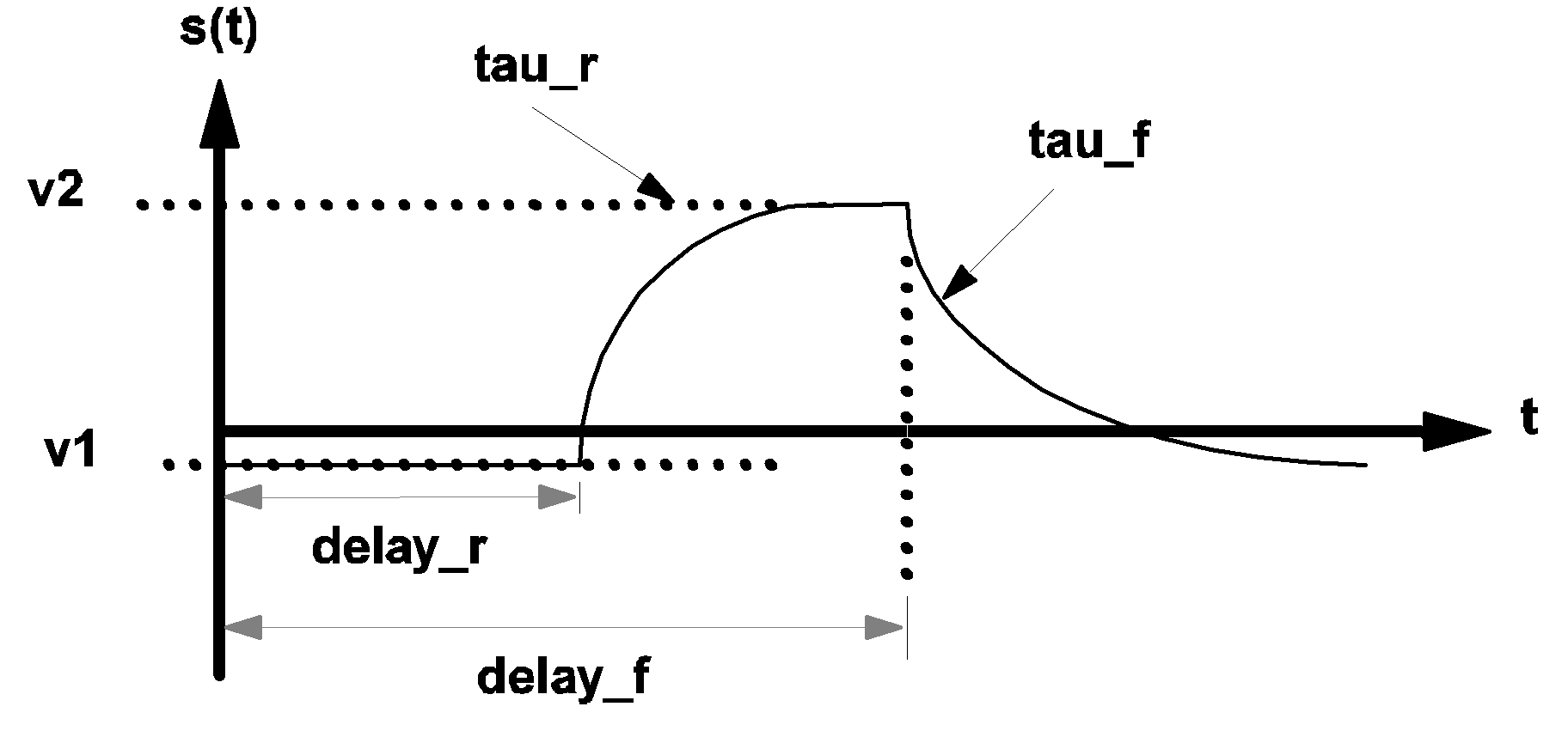 |
3.8 Waveform s(t) of an exponential pulse source |
Aperiodic Piecewise-Linear Sources
An aperiodic piecewise-linear source has its source function s(t) defined in terms of a finite number of linear segments. See diagram below for a typical example. The formats for independent aperiodic piecewise linear sources are:
Vname  n+  n-  PWL NSEG=k
+ X0=x0 Y0=y0 ... XK=xk YK=yk
and
Iname  n+  n-  PWL  NSEG=k
+ X0=x0 Y0=y0 ... XK=xk YK=yk
where
| V | is the one-character element keyword "V" for independent voltage sources |
| I | is the one-character element keyword "I" for independent current sources |
| name | is the individual name of the device |
| n+ | is the name of the positive node, and is a nonnegative integer |
| n- | is the name of the negative node, and is a nonnegative integer |
| PWL | is the three-character keyword "PWL" to signify that this is an aperiodic piecewise-linear source |
| NSEG= | is the five-character keyword "NSEG=" representing the number of linear segments for this source |
| k | is an integer defining the number of linear segments and can take on values from 2 to 253, inclusively |
| X0= | is the keyword "X0=" representing the time (or x axis) coordinate of the start of the first linear segment |
| x0 | is a floating-point number which defines the value of X0 in seconds |
| Y0= | is the three-character keyword "Y0=" representing the voltage or current (y axis) coordinate of the start of the first linear segment |
| y0 | is a floating-point number which describes the value of Y0 in volts for a voltage source and in amperes for a current source |
| X1= | is the keyword "X1=" representing the time (or x axis) coordinate of the end of the first linear segment and the start of the second linear segment |
| x1 | is a floating-point number which describes the value of X1 in seconds. x1 is larger than or equal to x0 |
| Y1= | is the keyword "Y1=" representing the voltage or current (y axis) coordinate of the end of the first linear segment and the start of the second linear segment |
| y1 | is a floating-point number which describes the value of Y1 in volts for a voltage source, and in amperes for a current source |
| X2= | is the keyword "X2=" representing the time (or x axis) coordinate of the end of the second linear segment and the start of the third linear segment |
| x2 | is a floating-point number which defines the value of X2 in seconds. x2 is larger than or equal to x1 |
| Y2= | is the keyword "Y2=" representing the voltage or current (y axis) coordinate of the end of the second linear segment and the start of the third linear segment |
| y2 | is a floating-point number which defines the value of Y2 in volts for a voltage source, and in amperes for a current source, and so on |
The source value ???MATH???s(t)???MATH??? for ???MATH???t < x0???MATH??? is set to ???MATH???s(t) = y0???MATH???. The source value ???MATH???s(t)???MATH??? for ???MATH???t > xk???MATH??? is set to ???MATH???s(t) = yk???MATH???.
An example of the waveform ???MATH???s(t)???MATH??? of a piecewise-linear source is illustrated in the diagram below.
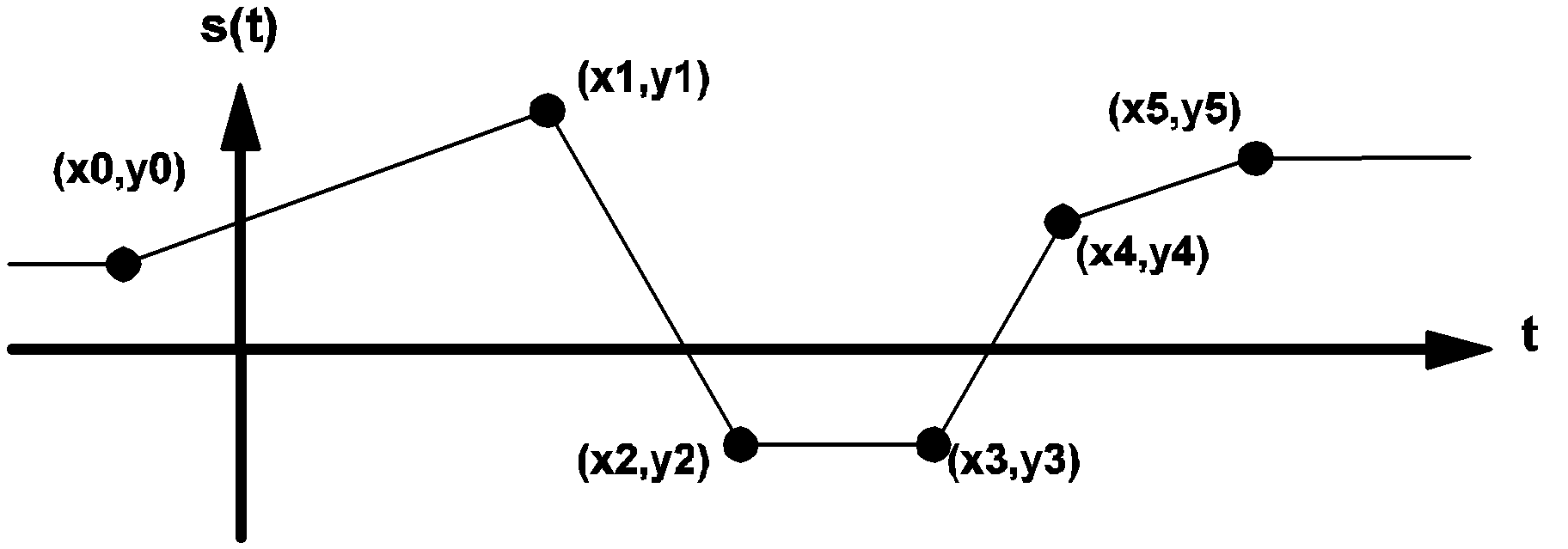 |
3.9 Example of the waveform s(t) of a typical piecewise-linear source |
Mutual Inductances
The format for mutual inductance is:
M-Lname1-Lname2 valuewhere
| M | is the one-character element keyword "M" for mutual inductors |
| - | is the hyphen character ('-') |
| Lname1 | is the device name of a linear inductor defined in the current circuit |
| Lname2 | is the device name of another linear inductor defined in the current circuit. Lname1 and Lname2 must refer to different inductors |
| value | is a floating-point number assigned as the mutual inductance between the two linear inductors |
L1 3 1 200U IC=50M
L2 4 2 500U IC=0
LA 101 100 1M IC=-30U
LB 210 17 2M IC=10U
M-L1-L2 15U
M-LA-LB -30U
The mutual inductance between two linear inductors is positive if the polarity dots appear on the positive nodes of both inductors or if the polarity dots appear on the negative nodes of both inductors. In the example shown below, the mutual inductance between inductors LA and LB is negative because the polarity dot is located at the positive node of LA but the polarity dot is located at the negative node of LB.
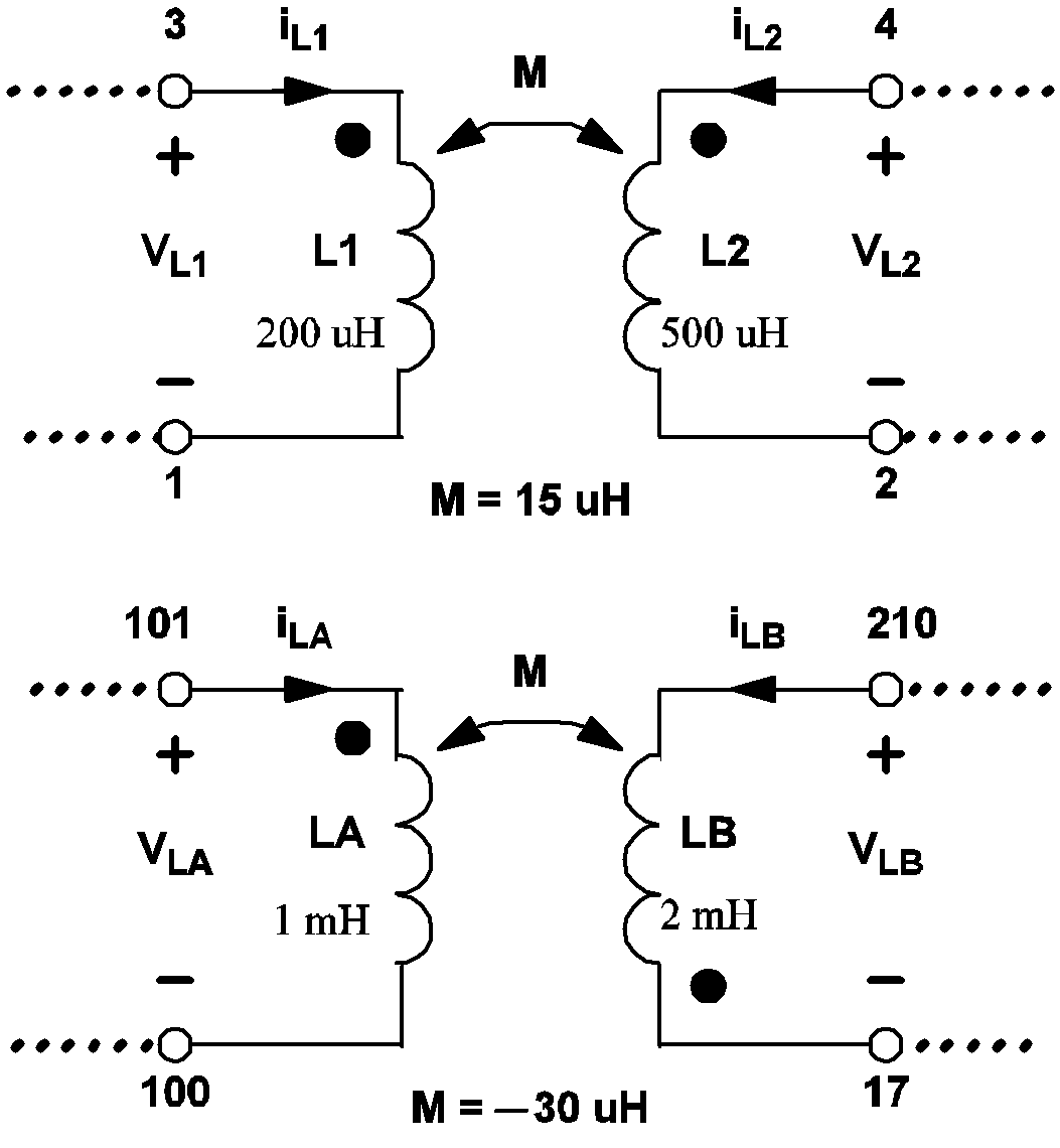 |
3.10 Examples of the definitions for mutual inductances |
Linear Voltage-Controlled Sources
The formats for voltage-controlled sources are:
Ename n+ n- nc+ nc- value
Gname n+ n- nc+ nc- value
Ename n+ n- cname value
Gname n+ n- cname valuewhere
| E | is the one-character element keyword "E" for linear voltage-controlled voltage sources |
| G | is the one-character element keyword "G" for linear voltage-controlled current sources |
| name | is the individual name of the device |
| n+ | is the name of the positive node of the controlled source, and is a nonnegative integer |
| n- | is the name of the negative node of the controlled source, and is a nonnegative integer |
| nc+ | is the name of the positive controlling node in the same circuit where the linear voltage-controlled source is being defined |
| nc- | is the name of the negative controlling node in the same circuit where the linear voltage-controlled source is being defined |
| cname | is the name of a controlling device in the same circuit where the linear voltage-controlled source is being defined |
| value | is a floating-point number assigned as the proportionality constant for this controlled source |
\[ s=\textit{value}*v(nc+,nc-) \] where ???MATH???v(nc+, nc-)???MATH??? represents the voltage of node nc+ with respect to node nc-, and s is the controlled voltage for a controlled voltage source and the controlled current for a controlled current source. In the second format, the value of the controlled source is given by
\[ s=\textit{value}*v(\textit{cname}) \] where v(cname) represents the branch voltage across the positive and negative nodes of the controlling device named "cname".
Linear Current-Controlled Sources
The formats for current-controlled sources are:
Hname n+ n- cname value
or
Fname n+ n- cname valuewhere
| H | is the one-character element keyword "H" for linear current-controlled voltage sources |
| F | is the one-character element keyword "F" for linear current-controlled current sources |
| name | is the individual name of the device |
| n+ | is the name of the positive node of the controlled source and is a nonnegative integer |
| n- | is the name of the negative node of the controlled source and is a nonnegative integer |
| cname | is the name of a controlling device and is not restricted to a voltage source |
| value | is a floating-point number assigned as the proportionality constant for this controlled source |
\[ s=\textit{value}*i(\textit{cname}) \] where i(cname) represents the branch current through the controlling device named "cname".
Ideal Transformers
The format for ideal transformer differs from the typical format defined in Device Statement Format:
!Tname  N_WIND=k  n1+  n1-  N1=t1 ...
+ nk+  nk-  Nk=tk
where
| !T | is the two-character element keyword "!T" for ideal transformers |
| name | is the individual name of the device |
| N_WIND= | is the seven-character keyword "N_WIND=" representing the number of windings in the transformer |
| k | is a positive integer assigned as the number of windings and can assume any integral value from 2 to 255, inclusively |
| n1+ | is a nonnegative integer to represent the node name of the "dotted" terminal of winding 1 |
| n1- | is a nonnegative integer to represent the node name of the "undotted" terminal of winding 1 |
| N1= | is the three-character keyword "N1=" representing the number of turns in winding 1 |
| t1 | is a positive floating-point number assigned as the number of turns in winding 1 |
Simple Switches
The formats for simple switches are:
Sname  n+  n-  nc+  nc-  mname  IC={CLOSE|OPEN}

Sname  n+  n-  cname  mname  IC={CLOSE|OPEN}
where
| S | is the one-character element keyword "S" for simple switches |
| name | is the individual name of the device |
| n+ | is the name of the positive node of the simple switch and is a nonnegative integer |
| n- | is the name of the negative node of the simple switch and is a nonnegative integer |
| nc+ | is the name of the positive controlling node |
| nc- | is the name of the negative controlling node |
| cname | is the name of a controlling device |
| mname | is the name of a compatible switch model |
| IC= | is the three-character keyword "IC=" representing the initial condition of the simple switch |
| OPEN | is the four-character keyword "OPEN", meaning the simple switch is initialized to the open state |
| CLOSE | is the five-character keyword "CLOSE", meaning the simple switch is initialized to the closed state (use of OPEN and CLOSE are mutually exclusive) |
In SIMPLIS, both the voltage-controlled and the current-controlled switches are modeled by the simple S switch. If the switch model named "mname" has a model type of VCSW, the switch is considered to be voltage controlled. If the model type of the switch model is ICSW, the switch is considered to be current controlled.
The initial condition provided for a simple switch is only used by SIMPLIS as a suggestion. If the circuit condition on the controlling variable dictates a different initial condition, SIMPLIS automatically overrides the given initial condition with the correct initial condition.
Simple Transistor Switches
The formats for simple transistor switches are:
Qname  n+  n-  nc+  nc-  mname  IC={CLOSE|OPEN}

Qname  n+  n-  cname  mname  IC={CLOSE|OPEN}
where
| Q | is the one-character element keyword "Q" for simple transistor switches |
| name | is the individual name of the device |
| n+ | is the name of the positive node of the simple transistor switch and is a nonnegative integer |
| n- | is the name of the negative node of the simple transistor switch and is a nonnegative integer |
| nc+ | is the name of the positive controlling node |
| nc- | is the name of the negative controlling node |
| cname | is the name of a controlling device |
| mname | is the name of a compatible transistor switch model |
| IC= | is the three-character keyword "IC=" representing the initial condition of the simple transistor switch |
| OPEN | is the four-character keyword "OPEN", meaning the simple transistor switch is initialized to the open state |
| CLOSE | is the five-character keyword "CLOSE", meaning the simple transistor switch is initialized to the closed state |
There are four model types compatible with simple transistor switches. These are:
- VCQPOS
- VCQNEG
- ICQPOS
- ICQNEG
Model types VCQPOS and VCQNEG correspond to voltage-controlled transistor switches. Model types ICQPOS and ICQNEG correspond to current-controlled transistor switches.
Similar to the initial condition given to a simple switch, the initial condition given to a simple transistor switch is used by SIMPLIS only as a suggestion. Giving a correct initialization, however, eliminates the computation time required by SIMPLIS to search for the correct initial state, and thus leads to a faster simulation.
Piecewise Linear Resistors
The format for piecewise-linear resistor is:
!Rname n+ n- mname IC=seg_numwhere
| !R | is the two-character element keyword "!R" for piecewise-linear resistors |
| name | is the individual name of the device |
| n+ | is the name of the positive node and is a nonnegative integer |
| n- | is the name of the negative node and is a nonnegative integer |
| mname | is the name of a model compatible with a piecewise-linear resistor |
| IC= | is the three-character keyword "IC=" representing the initial segment of operation for the piecewise-linear resistor |
| seg_num | is a positive integer assigned as the initial segment of operation for the piecewise-linear resistor. It must be larger than or equal to 1, and less than or equal to the number of segments defined in the model. |
There are two types of models that are compatible with piecewise-linear resistors: VPWLR for voltage-defined piecewise-linear resistors and IPWLR for current-defined piecewise-linear resistors.
The initial segment of operation is used by SIMPLIS as a suggestion. SIMPLIS automatically computes the circuit voltages and currents to determine the correct initial segment of operation.
Piecewise-Linear Inductors and Capacitors
The formats for piecewise-linear inductors and piecewise-linear capacitors are:
!Lname  n+  n-  mname  IC=init_cond

!Cname  n+  n-  mname  IC=init_cond
where
| !L | is the two-character element keyword "!L" for piecewise-linear inductors |
| !C | is the two-character element keyword "!C" for piecewise-linear capacitors |
| name | is the individual name of the device |
| n+ | is the name of the positive node and is a nonnegative integer |
| n- | is the name of the negative node and is a nonnegative integer |
| mname | is the name of a model compatible with a piecewise-linear inductor or a piecewise-linear capacitor |
| IC= | is the three-character keyword "IC=" representing the initial condition |
| init_cond | is the value of initial condition. It is the initial current (in amperes) in the case of a piecewise-linear inductor and the initial voltage (in volts) in the case of a piecewise-linear capacitor. |
Simple Logic Gates
The format for a simple logic gate is:
!Dname no1 no2 ... nref ni1 ni2 ... mname IC={0|1}
where
| !D | is the two-character element keyword "!D" for simple logic gates |
| name | is the individual name of the device |
| no1 | is a nonnegative integer representing the name of the first output node of the logic gate |
| no2 | is a nonnegative integer representing the name of the second output node of the logic gate if there is more than one output |
| nref | is a nonnegative integer representing the name of the reference node. The logic state(s) of the output(s) of a simple logic gate are defined in terms of the voltage(s) of the output node(s) with respect to the reference node. The logic state(s) of the input(s) of a simple logic gate are defined in terms of the voltage(s) of the input node(s) with respect to the reference node |
| ni1 | is a nonnegative integer representing the name of the first input node of the logic gate |
| ni2 | is a nonnegative integer representing the name of the second input node of the logic gate if there are more than one input |
| mname | is the name of a model compatible with a simple logic gate |
| IC= | is the three-character keyword "IC=" representing the initial output state of the logic gate |
| 0 | is the integer 0 to indicate that the initial output state of this gate is logic 0 |
| 1 | is the integer 1 to indicate that the initial output state of this gate is logic 1 (use of the 0 and 1 are mutually exclusive) |
The model types and the associated simple logic gates are summarized in the table below.
| Model Type | Gate Type | Num. Inputs | Num. Outputs |
| INV | Inverter | 1 | 1 |
| COMP | Comparator | 2 | 1 |
| XOR | Exclusive OR gate | 2 | 1 |
| ORk | k-input OR gate 2 ???MATH???\leq???MATH??? k ???MATH???\leq???MATH??? 9 | k | 1 |
| NORk | k-input NOR gate 2 ???MATH???\leq???MATH??? k ???MATH???\leq???MATH??? 9 | k | 1 |
| ANDk | k-input AND gate 2 ???MATH???\leq???MATH??? k ???MATH???\leq???MATH??? 9 | k | 1 |
| NANDk | k-input NANDk gate 2 ???MATH???\leq???MATH??? k ???MATH???\leq???MATH??? 9 | k | 1 |
| SRFF | Set-Reset Flip Flop | 2 | 2 |
| CLK_SRFF | Clocked Set-Reset Flip Flop | 3 | 2 |
| CLK_JKFF | Clocked JK Flip Flop | 3 | 2 |
| CLK_DFF | Clocked D Flip Flop | 2 | 2 |
| CLK_TFF | Clocked Toggle Flip Flop | 2 | 2 |
| LATCH | Latch | 2 | 1 |
Subcircuit Calls / Instantiation
The format for a subcircuit call is:
Xname n1 n2 ... nn snamewhere
| X | is the one-character element keyword "X" for the subcircuit call/instantiation |
| name | is the individual name of the device |
| n1 | is a nonnegative integer to represent the name of the first node of this device |
| n2 | is a nonnegative integer to represent the name of the second node of this device |
| ◄ Overview | Overview ▶ |