1.0 Getting Started with the SIMPLIS Tutorial
This tutorial follows the progression of a buck converter design from first constructs to a final, parametrized, hierarchical design. Although all schematics and supporting files can be downloaded as you proceed through the tutorial, a zip archive containing all files can be downloaded in the next section.
In this topic:
1.1 Downloading the Files
For this tutorial, you need a copy of the schematics and other supporting files as well as either the free introductory version, SIMetrix/SIMPLIS Elements, or a fully licensed version of SIMetrix/SIMPLIS. To request an evaluation license for the full version of SIMetrix/SIMPLIS, visit our Evaluation Page. SIMetrix/SIMPLIS Elements can be downloaded here.
If you already have SIMetrix/SIMPLIS on your computer, verify that you have at least version 8.20. To identify the version of your installation, select from the menu bar; a dialog opens and displays the current SIMetrix/SIMPLIS version.
To update to the most recent version, select from the menu bar.
Follow these steps to download the files for this tutorial:
- To download a zip file which includes all schematics used in this tutorial, click simplis_tutorial_examples.zip.
- To request an evaluation license for the full version of SIMetrix/SIMPLIS, visit our Evaluation Page.
SIMPLIS welcomes your feedback (positive, negative, bugs, etc.) regarding this tutorial. To send comments, click here.
1.2 Tips for Navigating this Tutorial
The SIMPLIS tutorial is intended to help new users get started with the SIMPLIS simulator and to serve as a general reference for SIMPLIS. If you are an experienced user, continue in this topic and follow the steps to set up the user interface for the rest of the tutorial; after completing this topic, feel free to skip ahead by clicking links in the left panel or by using the search box to find a keyword.
1.2.1 Navigation Conventions
Topics with subsections include a mini table of contents at the top of the page, similar to:
In this topic:
At the end of each section is a back-to-top link that you can use to return to the table of contents.
At the top of each page is a navigation bar indicating the hierarchical path of the current topic in the documentation system:

This path is updated every time you change topics, and each portion of text is a hyperlink which will take you to that topic or section of the larger documentation system.
On the right hand side of the navigation bar are two buttons which allow you to navigate within the tutorial.
- The
 arrow goes to the previous topic
in the tutorial.
arrow goes to the previous topic
in the tutorial. - The
 arrow goes to the next topic in
the tutorial.
arrow goes to the next topic in
the tutorial.
1.2.2 Text Conventions
The following text conventions are designed to help you scan the content:
- Bold text usually indicates something that you are to select on the screen or to type on the keyboard. File names are also in bold.
- Result information appears in green italic text to indicate what
should occur after you complete the instructions in a numbered step.Result: Green italic text ...
- Menu selections appear with a > separating the menu items. For
example, indicates the following instruction:
From the menu bar, click File and then select Save Schematic .
1.2.3 Schematic Images
- The Hide grid option is off by default. Leaving the grid visible as you work can help you place symbols and wire them together on the schematic.
- The Schematic editor menu turns on and off the grid.
1.3 SIMetrix/SIMPLIS Environment
The SIMetrix/SIMPLIS software package comes with two simulators:
- The SIMetrix Simulator is an optimized SPICE simulator with excellent convergence.
- The SIMPLIS Simulator, the one used in this tutorial, is a Piecewise-Linear (PWL) simulator optimized for switching power supply design.
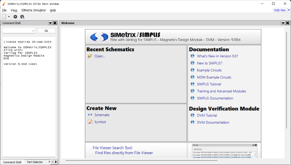
Beginning with SIMetrix/SIMPLIS version 8.0, SIMetrix/SIMPLIS has an integrated user interface with a single Main Window and a set of sub windows called System Windows which can be moved or docked on the periphery of the main window.
- The Welcome Page contains links to open recently used files, to access the documentation system, etc.
- The Schematic Editor window allows you to edit schematics.
- The Waveform Viewer window opens to display output curves after you have run a simulation.
- The Symbol editor window is where you use to create or modify symbols.
The System Windows include these:
- The Command Shell displays error messages. Note: In the full versions of SIMetrix/SIMPLIS, the Command Shell includes a text field for entering script commands.
- The Part Selector is where you find symbols to place on a schematic. The part selector is populated with symbols based on the simulator mode of the schematic (SIMetrix or SIMPLIS).
- The File View allows easy access to your file system for opening files in SIMetrix/SIMPLIS. You can add your commonly used directories to the file viewer.
1.4 Setting General Options
SIMPLIS comes with default options that affect various aspects of how you work. For the purpose of this tutorial, you need to change the simulator mode so each new schematic will use the SIMPLIS simulator. You control all options through the SIMetrix/SIMPLIS Main Window menus or toolbar buttons.
To change the default simulator mode, follow these steps:
- Start up SIMetrix/SIMPLIS from the Start menu. Result: The SIMetrix/SIMPLIS Main Window opens.
- On the SIMetrix/SIMPLIS Main Window, click .
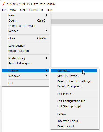
- Highlight
Options
and then click
General...
. Result: The Options/Preferences dialog box opens showing the Schematic tab.
- Go to the Initial Simulator section in the upper-right corner, and click the
SIMPLIS radio button.
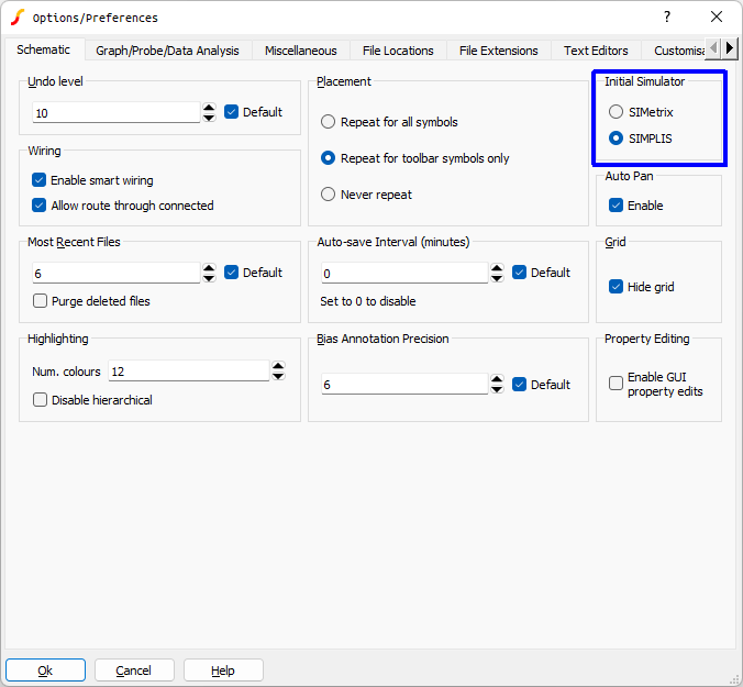
- Click Ok. Result: Your simulator preference has been saved to your user profile and will persist after you close SIMetrix/SIMPLIS. You may have also noticed the Welcome Page was refreshed after you clicked Ok on the dialog. In particular, the icon at the top of the page changed from the SIMetrix icon to the SIMPLIS icon. In the Create New section of the Welcome Page, the icon next to the Schematic link also changed to a SIMPLIS icon, indicating that each new schematic created will use the SIMPLIS simulator.
1.5 Showing the Part Selector
The default SIMetrix/SIMPLIS configuration has the part selector system window hidden. In this tutorial, you will place symbols from the part selector, so you need to make the Part Selector visible before you start placing symbols.
To show the Part Selector, select the menu.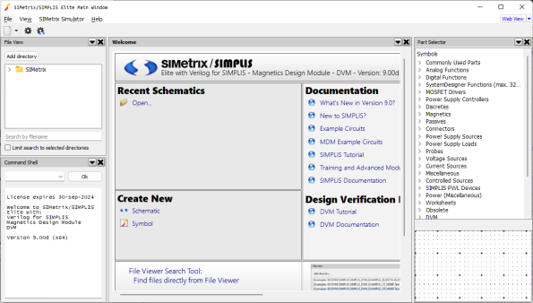
1.6 Setting up the User Interface for the Tutorial
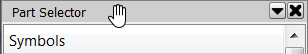
- Move the mouse cursor to the gray bar at the top of the Part Selector system
window.Result: The mouse cursor changes from a pointer to a open hand.
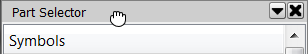
- Press and hold the left mouse button.Result: The open hand closes and the Part Selector system window is ready to be moved.
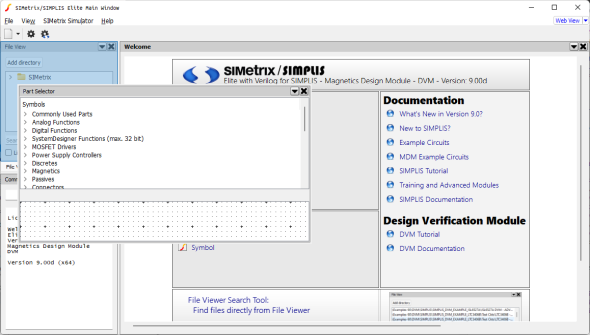
- While holding down the left mouse button, drag the Parts Selector system window
to the left. As you drag the window, you will notice areas of the main window will
turn light blue. This is an indicator of the location where the system window will
be placed after the left mouse button is released. In the following image, the
Part Selector system window will be placed on the left hand side of the main
window, in a tab stack with the File View system window:
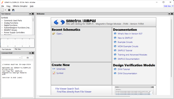
- Release the mouse button to place the Part Selector system window on the File
View system window.Result: The Part Selector and File View system windows are tabbed in a single system window:
- Repeat the process for the Command Shell system window, dragging it to the other
two system widgets.Result: All three system windows are tabbed together in a single window. This system window configuration will be used for the rest of the tutorial.
1.7 Creating a New Schematic
To create a new schematic, follow these steps:
- On the Welcome Page, in the Create New section, click
Schematic.
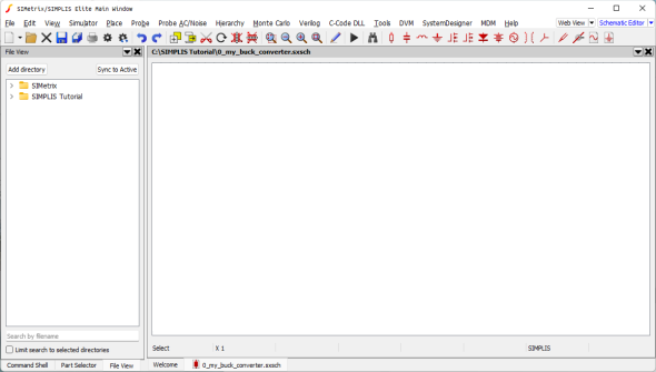
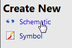 Result: A new schematic opens.
 - Check the lower right corner to verify that the mode is SIMPLIS.
1.8 Saving your Schematic
At this point you have a blank schematic with the simulator mode set to SIMPLIS. To save your schematic, follow these steps:
- Select
- Navigate to a convenient location to use as a working directory where you can save the schematics that you create in this tutorial. In the tutorial text, the directory used will be C:\SIMPLIS Tutorial.
- Name the file 0_my_buck_converter.sxsch.
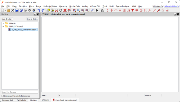
1.9 Add Working Directory to the File View
It will be easier to access the schematic files used in the tutorial if you add the working directory to the File View system window. To add the directory to the File View, follow these steps:- Click on the File View tab in the system window.Result: The File View system window comes into focus.
- Click on the Add Directory button.Result: A directory browser window opens to the current directory.
- On the directory browser, click Select FolderResult: The directory is added to the File View system window.
- To see the contents of any directory in the File View, simply double click on the
directory.Result: The directory contents are displayed with the 0_my_buck_converter schematic being the only schematic file in the directory.