Appendix 5.C - Tabbed Dialog Spreadsheet Tool
To download the examples for Module 5, click Module_5_Examples.zip.
In this topic:
Using the Tabbed Dialog Spreadsheet Tool
Version 8.50 introduced an internal tool to assist with creating Tabbed and Radio Select Dialogs. Because of this, the Spreadsheet tool is no longer needed. However, this appendix has been retained for reference.
Exercise #1: The TabValueDialog Spreadsheet
This exercise walks you through the structure of the spreadsheet to help you understand the process.
- Open the spreadsheet 5.4_tab_value_dialog_definition_worksheet.xlsx located in the C:\Training\Module_5_Examples directory.
- Notice that the spreadsheet is broken down into 5 numbered steps:
- Step #1 defines the type of dialog: Tabbed or Radio Select
- Step #2 defines the tabs
- Step #3 defines the groups
- Step #4 defines the labels
- Step #5 defines the descriptions
- Notice that the same formatting is used as with the basic dialogs:
- User inputs are formatted as follows:
- Calculated cells are shown with this format:

- User inputs are formatted as follows:
- Six script commands are concatenated in cells B43~B48. When executed in SIMetrix/SIMPLIS, these commands add (or change) the symbol properties to the symbol that is currently open in the Symbol Editor.
In the next exercise you will add the tabbed parameter-editing dialog to the parameterized RC filter symbol.
Exercise #2: Add Parameter-Editing Dialog
As with the Basic Add Parameter-Editing Dialog Exercise, you will copy a set of script commands from the spreadsheet and execute the commands in SIMetrix/SIMPLIS.
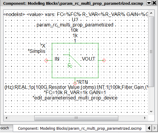
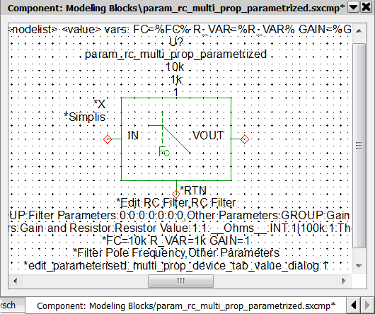
- Open the schematic 5.5_parametrized_rc_filters_multi_prop_dialogs.sxsch . This example is pre-prepared with the Multi-Property parameterization method. The only part missing is the parameter editing dialog.
- To add the parameter-editing control definitions to the symbol for the
parameterized RC filter, follow these steps:
- On the SIMetrix/SIMPLIS schematic, select the symbol for U2.
- To open the schematic component in the Symbol Editor, type the keyboard
shortcut Shift+S, or right click and select Edit Symbol....
Result: The symbol opens in the Symbol Editor with the NewValueDialog definition properties.
- Navigate to the spreadsheet window, and select the red text in cells
B43~B48.Result: The selected cells should appear as follows:
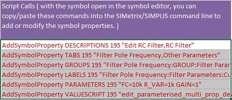
- Press Ctrl+C to copy the cells to the windows clipboard. Result: The selected cells have an animated border indicating the cells are selected.
- Navigate to the SIMetrix/SIMPLIS command shell window.
- Click the mouse in the command line entry located at the top of the command
shell window:
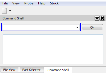
- Press Ctrl+V to paste the commands in the command line. Result: The last part of the command string is visible in the command line:
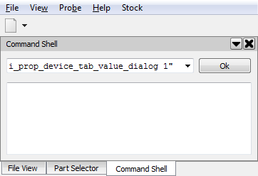
- Press Enter, or click Ok on the command line. Result: The commands are executed in SIMetrix/SIMPLIS. Each AddSymbolProperty command adds a single symbol property to the symbol. Each ChangeSymbolProperty modifies the existing property. The commands apply the Hidden and Protected property flags and add the parameters below the symbol.Note: This step overwrites the previous NewValueDialog definition.
- Press Ctrl+S to save the symbol, and then click Ok on the Save Symbol dialog.
- Navigate to the Schematic Editor window. Double click on U2, which is the
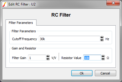
RC filter attached to the multi-prop(30kHz) probe. Result: The parameter-editing dialog opens:
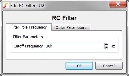
- Select the Other Parameters tab and change the Resistor Value to 10k.
- Click Ok to save your changes. Result: The parameter value for R_VAR changes to 10000 on the schematic.Note: The parameter-editing control for the resistor value is currently an integer type control, which returns numbers in non-engineering notation.
Exercise #3: Modify The Dialog Definition
In the previous exercise, you added a parameter-editing definition saved in the spreadsheet. This definition used three control types as a demonstration; however, the parameters being edited should be REAL types. In this exercise you will modify the dialog definition to use the REAL type control for all parameters. You will also move the three filter parameters onto one tab but inside two group boxes.
- Navigate to the spreadsheet window.
- To delete the Other Parameters tab, select cell B14.
- Right click to bring up the context menu and select Delete > Table
Rows:
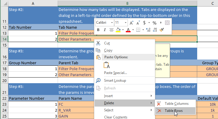 Result: Row 14 defining the Other Parameters tab is removed from the tabs table.Note: Whenever you add or remove tabs, groups, or parameter editing controls, you must add or delete rows from the excel tables.
 - To rename the single remaining tab, change the text in cell B13 from
Filter Pole Frequency to Filter Parameters.Note: You will now need to redefine all groups and parameters, as the groups and parameters use tabs which no longer exist.
- To move both group boxes to the new Filter Parameters tab, select Filter
Parameters from the drop-down menu in cells B17 and B18.
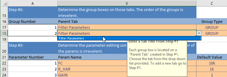
- To move the Gain and Resistor group below the Filter Parameters group
box, change cells G18 and I18 to 1. Result: This will move the Gain and Resistor group box to the second row on the Filter Parameters tab, below the existing Filter Parameters group defined on row 17.
- To move each parameter editing control to the group boxes on the Filter Parameters tab, select Filter Parameters from the drop-down menu in cells J22, J23, andJ24.
- To change the parameter editing control to real-valued spinners, change the content of cells H23 and H24 to REAL.
- Delete the contents of cell I24, which is the range entry for the Gain
parameter. Result: Without a range entry, any gain, including negative gain, can be entered in the parameter-editing control.
- Copy the commands in cells B42~B47, and paste the commands into the SIMetrix/SIMPLIS command line.
- Press enter or click Ok on the command line.
- Press Ctrl+S to save the symbol, and then click Ok on the Save Symbol dialog.
- Double click on the RC Filter symbol. Result: The modified dialog opens. Each control type is a Real type, and the controls are all on one tab.
- Click Ok. Result: On the schematic, the value of the Resistor Value parameter R_VAR changes from 10000 to 10k. The REAL type parameter editing control returns values formatted in engineering notation.