SystemDesigner Mux - 2, 3, and 4 Input
The SystemDesigner Mux models a selection multiplexer with two to four SystemDesigner bus inputs and a 32-bit signed-integer or floating-point result. From the Output parameter box, you can limit the resulting output to either signed or unsigned numbers with fewer than 32 bits.
The propagation delay can be defined as a fixed time, as asynchronous to any clock, or as a synchronous delay where the delay is a number of SystemDesigner -clocks cycles. In this release of SystemDesigner , the synchronous delay is supported only for integer-sampled data simulations.
In this topic:
| Model Name: | SystemDesigner Mux | |||||||
| Simulator: | This device is compatible with the SIMPLIS simulator. | |||||||
| Parts Selector Menu Location: | ||||||||
| Symbol Library: | SIMPLIS_SystemDesigner.sxslb | |||||||
| Model Library: | SIMPLIS_SystemDesigner.lb | |||||||
| Subcircuit Names: |
|
|||||||
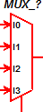
| Symbols: |
|
|||||||
| Multiple Selections: | Only one device at a time can be edited. | |||||||


Editing the SystemDesigner Mux
To configure the SystemDesigner Mux, follow these steps:
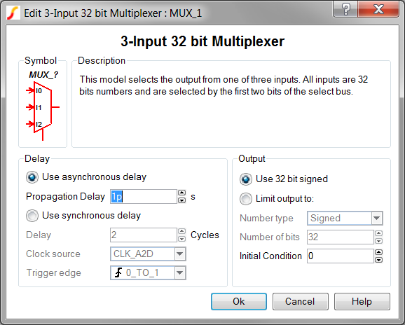
- Double click the symbol on the schematic to open the editing dialog to the Parameters tab.
- Make the appropriate changes to the fields described in the table below the image.
| Label | Parameter Description |
| Use asynchronous delay | Implements a combinatorial model where the output voltage changes in response to the input voltage change after a propagation delay. |
| Propagation delay | The propagation delay from an input change to an output change in seconds. This parameter is used only in models with Asynchronous delay. |
| Use synchronous delay | In response to an input voltage change, the output voltage changes after a designated number of clock cycles. |
| Delay | The propagation delay from an input change to an output change in number of clock cycles. The output will not change until the number of clock cycles has been reached. The output will then change state only on the selected Clock source edges specified by Trigger edge . This parameter is used only in models with Synchronous delay. |
| Clock source | Specifies the global clock used for the Mux. The Clock can be set up using the SystemDesigner->Edit SystemDesigner Clocks... menu item or by placing a Start of Conversion Breakin. |
| Trigger edge | Sets the Mux output to change on specific edges of the Clock:
|
Examples
The gain selection circuit using a 3-input Mux can be downloaded here: simplis_117_systemdesigner_mux_3_example.sxsch. In order to simulate this design, follow these steps:
- If you currently have a dialog box open in SIMetrix/SIMPLIS, cancel that dialog box so that the example can open in SIMetrix/SIMPLIS.
- Unzip the archive to a location on your computer.
- To open the schematic, double click the .sxsch file or drag that file into the SIMetrix/SIMPLIS Command Shell.
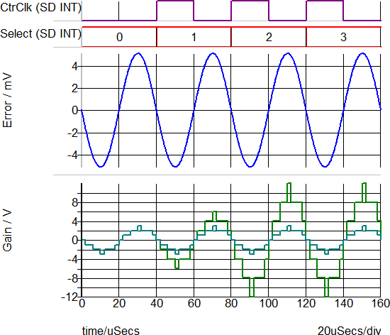
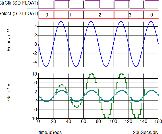
Waveforms
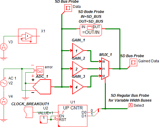
The circuit example below uses a Mux to select from three gain values, 1, 2, or 4. The Input voltage to the ADC is a sine wave with the following parameters:
- Amplitude = +/- 5.1mV
- Period = 40us
The ADC output has a peak value of +/- 3 LSB counts. This peak value is gained by the three gain blocks, and then the 3-input Mux selects one of the gained values to output.
The counter used in this example is a conventional SIMPLIS up-type counter; as such, the output bus from the counter is only two bits wide. A bus ripper is used to connect the counter to the Select input of the Mux. The selection of the inputs is decoded as follows:
| Select Input in Decimal | Input Selected |
| 0 | I0 |
| 1 | I1 |
| 2 | I2 |
| 3 | I2 |
The clock input of the counter is defined in the SystemDesigner Clocks dialog and appears on the schematic using the SystemDesigner Global Clock Breakout device. The clock has a 40us delay and the same frequency as the sine wave input source to the ADC, which is 25kHz.
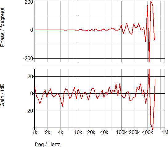
If you intend to use a gain-selection circuit similar to this example, make certain that the selection bus is constant for floating-point simulations because switching gain during a POP simulation causes the POP to fail to converge. In this example, the counter output is 0 for the POP and AC simulations; as such, the Mux selection will be I0, and the AC gain from the sampled data to the output of the Mux will be 0 dB because that is the gain of the I0 path of the Mux. If you change the initial condition of the counter to 1 or 2, you will see the gain change to 6dB and 12dB ,respectively.
The AC transfer function for the Mux is shown below. Note that the axis scales are fempto Degrees and fempto dB.