1st Order Discrete Time Filter
The 1st Order Discrete Time Filter models a first order z-domain transfer function. The transfer function in the z-domain from the input I(z) to the output O(z) for the 1st order discrete filter is shown below:
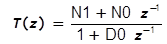
The difference equation representing this transfer function is

For example, if N1, N0, and D0 have been set to 0, 0.1, and -0.99, respectively, the resulting 1st order discrete filter will have a DC gain of 10.0, a pole located at z=0.99, and no zero.
The information in this topic refers to the latest 1st Order Discrete Time Filter which was introduced in version 8.10. In versions prior to 8.10, a similar Discrete Time Filter exists and has the same behavior as the new version. The new version simulates slightly faster than the old version, but the electrical behavior is identical. If you require a discrete time filter for use in versions prior to 8.10, the old 1st Order Discrete Time Filter can be placed from the part selector location: .
Related topics:
In this topic:
| Model Name: | 1st Order Discrete Filter | |||
| Simulator: | This device is compatible with the SIMPLIS simulator. | |||
| Parts Selector Menu Location: | ||||
| Symbol Library: | simplis_discrete_time_filters.sxslb | |||
| Model Library: | simplis_discrete_time_filters.lb | |||
| Subcircuit Name: | SIMPLIS_DTF_1POLE_FILTER_Y__V2 | |||
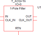
| Symbol: |
|
|||
| Multiple Selections: | Only one device at a time can be edited. | |||
Editing the 1st Order Discrete Filter
To configure the 1st Order Discrete Filter, follow these steps:
- Double click the symbol on the schematic to open the editing dialog to the Parameters tab.
- Make the appropriate changes to the fields described in the table below the image.
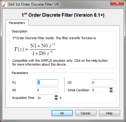
| Label | Parameter Description |
| N1 | Numerator constant term |
| N0 | Numerator coefficient for z -1 term |
| Acquisition Time | Filter acquisition time in seconds |
| D0 | Denominator coefficient for z -1 term |
| Initial Condition | Initial condition of the Discrete Time Filter output at time=0 |
Examples
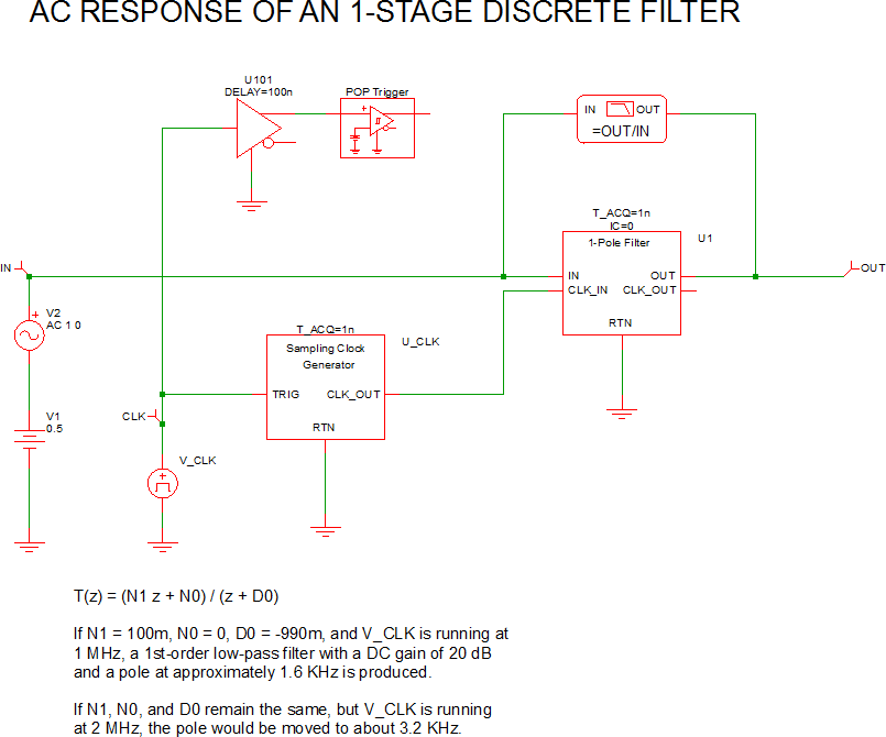
The test circuit used to generate the waveform examples in the next section can be downloaded here: simplis_034_1stordfilter_example.sxsch.
Waveforms
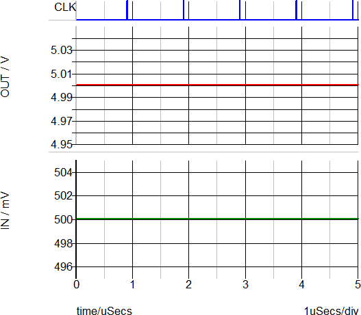
The POP waveforms below show that the DC input voltage to the filter is 0.5V and the DC output voltage is 5V, confirming that the DC gain of the 1st order discrete time filter is 10.
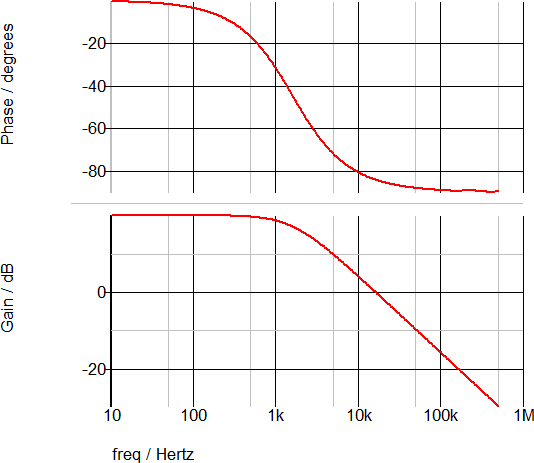
The following AC waveforms confirm that the DC gain is 20dB and the pole is approximately 1.6kHz.
Subcircuit Parameters
The subcircuit parameter names, data types, ranges, units, and descriptions are in the following table. The parameter names can be used to generate netlist entries for the device. For example, a valid 1st Order Discrete Time Filter netlist entry would be:
X$U1 18 21 0 20 0 SIMPLIS_DTF_1POLE_FILTER_Y__V2 vars: N1=0 IC=0 N0=0 D0=0 T_ACQ=1n
| Parameter Name | Label | Data Type | Range | Units | Parameter Description |
| D0 | D0 | String | none | Denominator coefficient for z -1 term | |
| IC | Initial Condition | Number |
|
none | Initial condition of the Discrete Time Filter output at time=0 |
| N0 | N0 | String | none | Numerator coefficient for z -1 term | |
| N1 | N1 | String | none | Numerator constant term | |
| T_ACQ | Acquisition Time | Number | min: 1f | s | Filter acquisition time in seconds |