Date
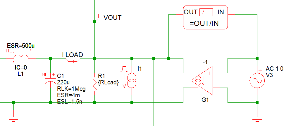
Part I Measuring the Output Impedance of a DC-DC Converter
Here, we employ the SIMPLIS POP and AC analyses to measure the Output Impedance of a DC-DC Converter. We demonstrate the test circuit required to add in parallel with the load in the DC-DC Converter schematic. We then show how this measurement process can be automated by properly configuring the SIMPLIS Power Supply Load.
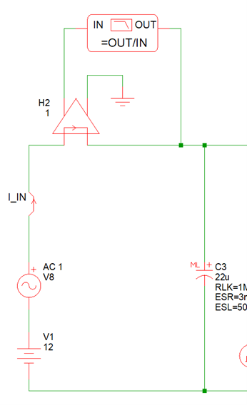
Part II Measuring the Input Impedance of a DC-DC Converter
Using the SIMPLIS POP and AC analyses, we demonstrate the test circuit that must be added to the schematic between the source and the input of the DC-DC Converter. This procedure can be automated by properly configuring the SIMPLIS Power Supply Source.
By properly configuring both the SIMPLIS Power Supply Source and Load, you can perform time-domain transient analyses as well as frequency-domain Input and Output Impedance measurements and Bode Plots of the control loop response, all with a single schematic.
Link to Webinar Recording
Part I - Output Impedance
The webinar recording can be viewed via:
- GoTo Webinar: Measuring the Output Impedance of a DC-DC Converter (26:11)
- Amazon CloudFront: Measuring the Output Impedance of a DC-DC Converter (26:11)
Part II - Input Impedance
The webinar recording can be viewed via:
- GoTo Webinar: Measuring the Input Impedance of a DC-DC Converter (23:33)
- Amazon CloudFront: Measuring the Input Impedance of a DC-DC Converter (23:33)
Reference Materials
Schematics and presentation slides for the webinar can be downloaded here: Nov_2025.zip