3.0.2 What Actual Device is Simulated in SIMPLIS?
In the previous topic, 3.0.1 What Happens When You Press F9?, you followed the process of netlist creation and netlist preprocessing to generate the final simulation deck file. In that topic you followed the expression {Rload} from symbol to netlist to the deck file where the expression {Rload} was evaluated and replaced with the numeric value 2.5.
In this topic you will learn how subcircuits can be defined in a library and how the netlist preprocessor copies these subcircuit definitions to the deck file. The netlist preprocessor searches the installed libraries for any subcircuit not already contained in the netlist, then copies the subcircuit definition from the library and inserts the definition into the deck file. Additionally, any parameters and expressions in the model definition are evaluated, resulting in the final model used in the simulation.
To download the examples for Module 3, click Module_3_Examples.zip
In this topic:
Key Concepts
This topic addresses the following key concepts:
- High-level models are created using subcircuits, which are a collection of primitive models (R/L/C) and possibly other subcircuits.
- Subcircuits can be included in the netlist file, or included in the deck by the netlist preprocessor.
- Subcircuits often use parameters which are passed into the subcircuit on the netlist instantiation line.
- Conditional .IF and .ELSE statements enable the model to be programmatically created based on parameter values.
What You Will Learn
In this topic, you will learn the following:
- How the preprocessor copies subcircuit definitions from the global library to the deck file.
- How parameters are passed into subcircuits.
- How parameters are used to dynamically create the resulting subcircuit definitions.
- How each subcircuit is made unique during netlist preprocessing.
- The basics of the subcircuit interface.
Getting Started
Almost all complex devices made up of more than a single primitive device are implemented as subcircuits. In this topic you will learn how subcircuits, when combined with parametrization, can be extremely powerful.
Exercise #1: Case Study - The Electrolytic Capacitor C1
In this exercise you will follow the path of the electrolytic output capacitor C1 from schematic symbol to netlist to deck file definition. The electrolytic capacitor model is built-into SIMetrix/SIMPLIS as a subcircuit library device. The preprocessor will copy the definition of the electrolytic capacitor from the library, preprocess any .IF and .ELSE statements in the model, and evaluate any expressions. The resulting text entered into the deck will have purely numerical values.
- Open the schematic 3.1_SelfOscillatingConverter_POP.sxsch.
- Press F9 to run the simulation.
- To get started, select the first output capacitor C1, and right click and
select the menu Edit/Add Properties... or use the keyboard shortcut
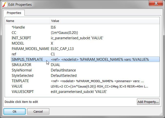
5.Result: The Edit Properties dialog for C1 opens:
 The Edit Properties dialog allows you to view or edit all properties for a
symbol. Symbol properties determine the instantiation line created in the netlist.
Two properties are of particular interest:
The Edit Properties dialog allows you to view or edit all properties for a
symbol. Symbol properties determine the instantiation line created in the netlist.
Two properties are of particular interest:- Because the MODEL is X, this symbol calls a model defined as a subcircuit. In comparison, a primitive capacitor in SIMPLIS has a MODEL property value of C.
- Because the symbol for C1 has a SIMPLIS_TEMPLATE property, this
property determines the netlist instantiation line for this device. The
SIMPLIS_TEMPLATE for the electrolytic capacitor is:
<ref> <nodelist> %PARAM_MODEL_NAME% vars: %VALUE%
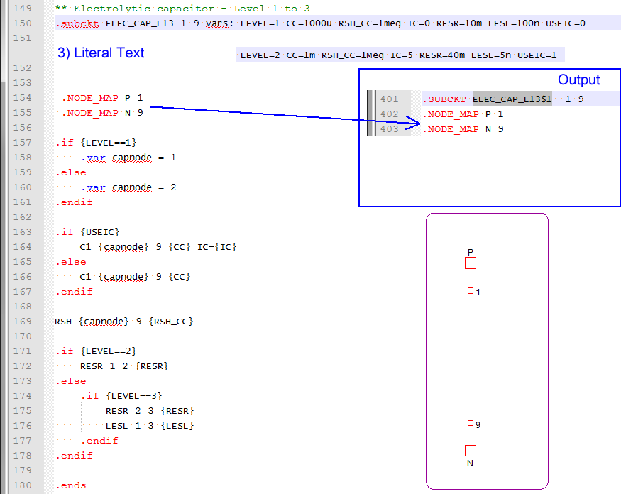
During the netlist process, the SIMPLIS_TEMPLATE property is resolved by the netlister. The netlister evaluates the template keywords enclosed in the greater-than and less-than brackets and substitutes literal properties enclosed in the percent signs, such as %PARAM_MODEL_NAME% and %VALUE%. Text which is not enclosed in the special characters, % and <>, is interpreted as literal text, and is passed on to the netlist without modification. There are several other template keywords, for a complete list, see: Template Property. Next, open the netlist file and find the netlist entry for C1.
- From the menu bar, select .Result: The Netlist file opens in the netlist editor.
- Use the shortcut key Ctrl+F to open the search dialog.
- Type C1
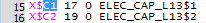
- Click on the Find Next button.Result: The document scrolls to line #40:
 The netlist entry created by the SIMPLIS_TEMPLATE is called the
instantiation, and this terminology will be used throughout the rest of the
course. The SIMPLIS_TEMPLATE and the netlist instantiation for C1 has five distinct
pieces, or tokens. These tokens are:
The netlist entry created by the SIMPLIS_TEMPLATE is called the
instantiation, and this terminology will be used throughout the rest of the
course. The SIMPLIS_TEMPLATE and the netlist instantiation for C1 has five distinct
pieces, or tokens. These tokens are: SIMPLIS_TEMPLATE Token Netlist Value <ref> X$C1 <nodelist> 17 0 %PARAM_MODEL_NAME% ELEC_CAP_L13 vars: vars: %VALUE% LEVEL=2 CC={1m*Gauss(0.20)} RSH_CC=1Meg IC=5 RESR=40m LESL=5n USEIC=1
Discussion: Exercise #1
The instantiation for C1 defines a number of things:
- Because the first character of the Reference designator is a X, this is a subcircuit.
- The capacitor is connected between nodes 17 and 0. Node 0 is ground on the schematic.
- The model used is called by name : ELEC_CAP_L13. This subcircut can be defined either in the netlist, the F11 window, an include file, in a local user library, or in this case, in a global SIMPLIS library.
- The vars: keyword tells the netlist preprocessor to pre-process the subcircuit using the optional parameters after the vars: keyword.
- The subcircuit has 7 parameters which are passed into the subcircuit definition.
These are the key-value pairs after the special vars: keyword:
Parameter Name Parameter Value LEVEL 2 CC {1m*Gauss(0.20)} RSH_CC 1Meg IC 5 RESR 40m LESL 5n USEIC 1
A key concept to understand is that the instantiation only defines which model is used, it's connectivity, and the optional parameters used. The electrical model definition is stored in one of the locations listed in item 3 above.
At this point the only thing missing is the actual definition for the electrolytic capacitor. In the next exercise you will view the model for the subcircuit capacitor ELEC_CAP_L13.
Exercise #2: The Library Definition for the Subcircuit ELEC_CAP_L13
- On the 3.1_SelfOscillatingConverter_POP.sxsch schematic, select C1. The capacitor symbol should turn blue indicating the capacitor is selected.
- Right click to bring up the context menu.
- Select the View Model menu item.Result: The model is copied from the global library to a temporary file, and opened in the netlist editor.
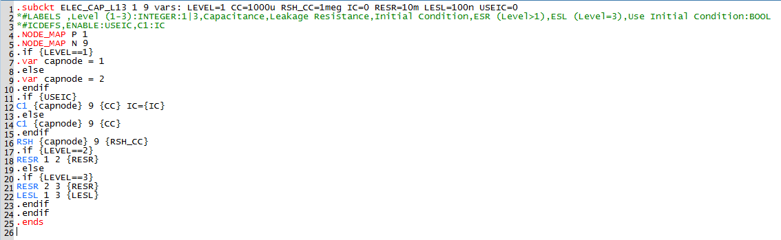
The model text defines the electrolytic capacitor model used by the every electrolytic capacitor symbol on this schematic. Note the distinction between a model and a symbol. The symbol creates a netlist instantiation line; the model is the electrical definition that is called by the instantiation.
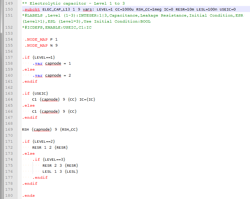
Every subcircuit definition in SIMPLIS begins with a .subckt statement, and ends with a .ends statement. As with almost everything in SIMetrix/SIMPLIS, the text is not case sensitive.
The first line defines the "subcircuit interface", that is:
- The subcircuit name.
- A list comprising the node number that each pin of this subcircuit is connected to.
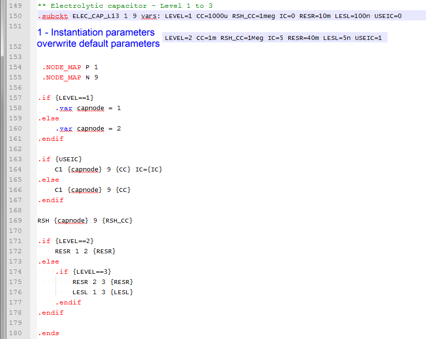
- The default parameter values. Parameter values passed into the subcircuit on the netlist instantiation line over-ride the default parameters on the .subckt line.
- The subcircuit definition has no reference designator. Instead the same definition is used by all instantiations in the netlist, only the parameters and connectivity to the top level circuit change.
- The nodes inside the subcircuit, in this case node numbers 1, 2, 3, and 9, are unique to that subcircuit. This means the same node numbers on the top level schematic are NOT connected to the same node numbers in the subcircuit. This critical concept cannot be over-emphasized! This allows you to isolate different portions of a circuit without any possibility of node numbers conflicting.
The netlist contains three electrolytic capacitor instantiations, with reference designators C1, C2, and C7. The two entries for C1 and C2 are:
In the next exercise you will see how the netlist preprocessor creates custom subcircuits for C1 and C2.
Exercise #3: The Deck Entries for C1 and C2
- From the menu bar, select .Result: The deck file opens in the netlist editor:
- Use the shortcut key Ctrl+F to open the search dialog.
- Type C1
- Click on the Find Next buttonResult: The deck file scrolls to line #15 where the instantiation line for C1 is located.
Notice the difference between the netlist and deck file instantiations as shown in the below:
| Netlist |
|
|
| Deck |
|
|
The two differences are ...
- The deck entries have no parameters - the parameters have been passed into the subcircuit and evaluated, creating a custom subcircuit for C1 and C2.
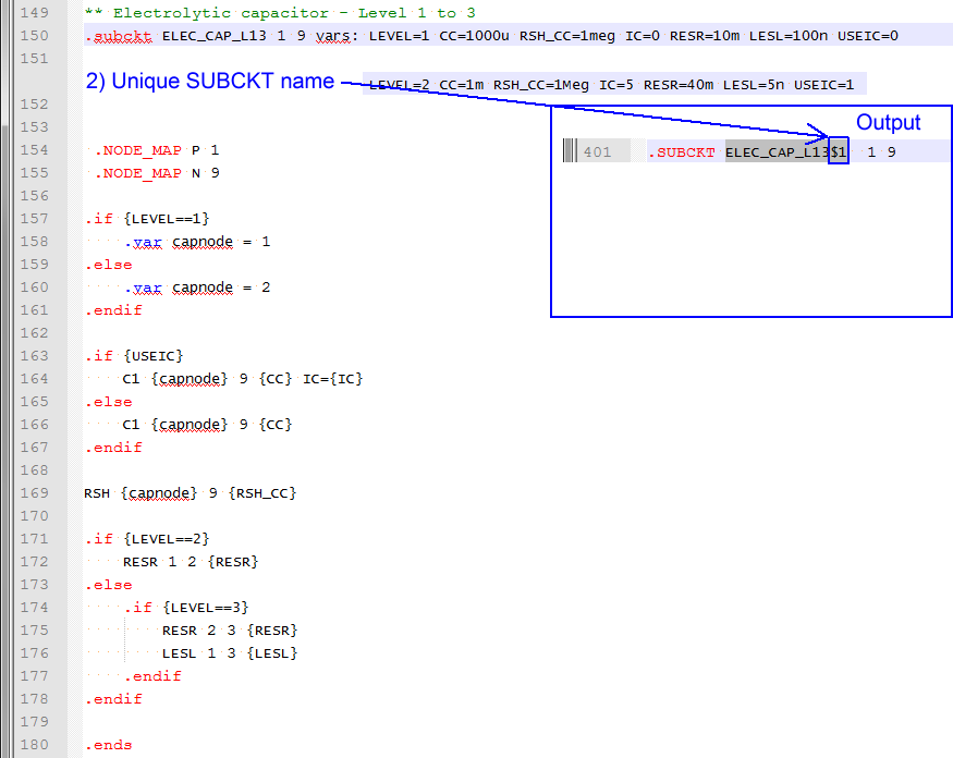
- The deck entries have a $1 and $2 appended to the subcircuit name - that is, two unique subcircuits have been created.
Next, look at the subcircuit definitions for the two subcircuits called by the deck instantiations for C1 and C2.
To search for ELEC_CAP_L13$1 in the netlist editor, follow these steps:
- Use the shortcut key Ctrl+F to open the search dialog.
- Type or copy from this text: ELEC_CAP_L13$1
- Click on the Find Next button twice.Result: The deck file scrolls to line 509 where the netlist preprocessor has placed the subcircuit for C1:
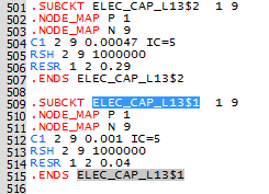
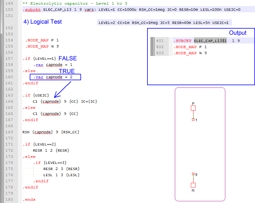
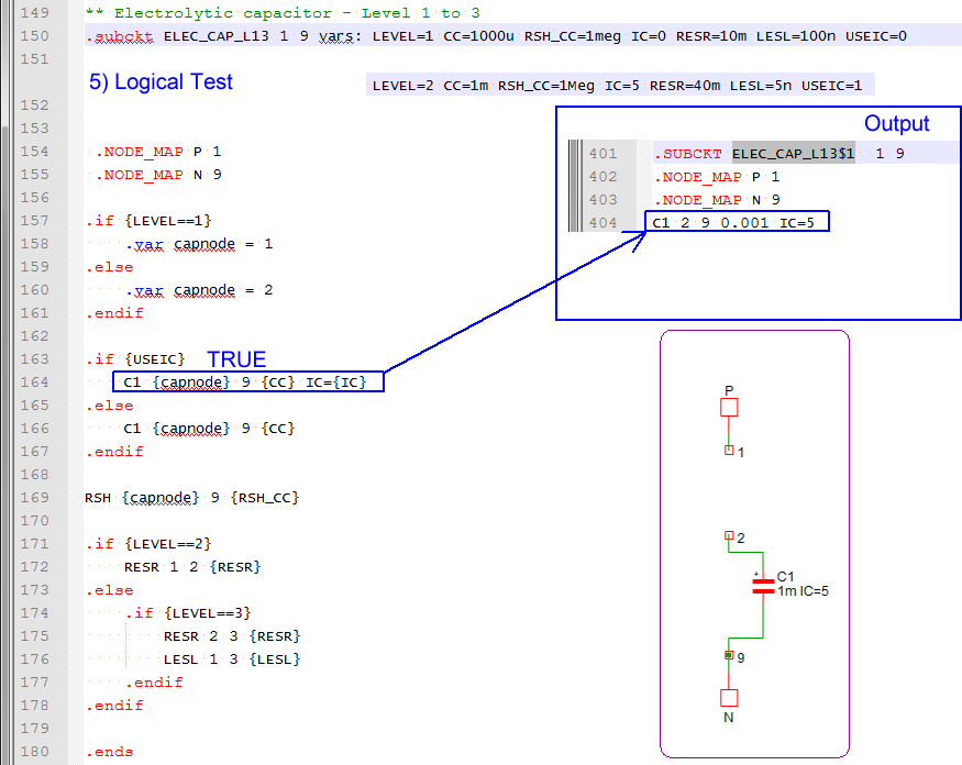
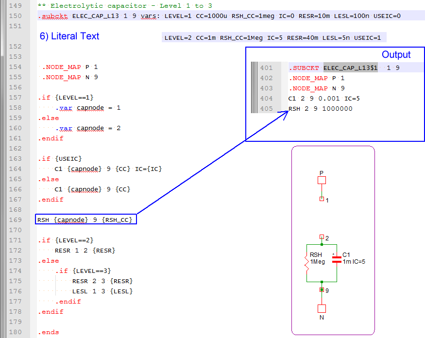
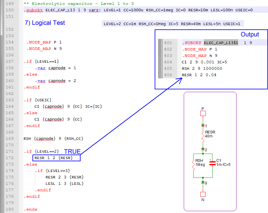
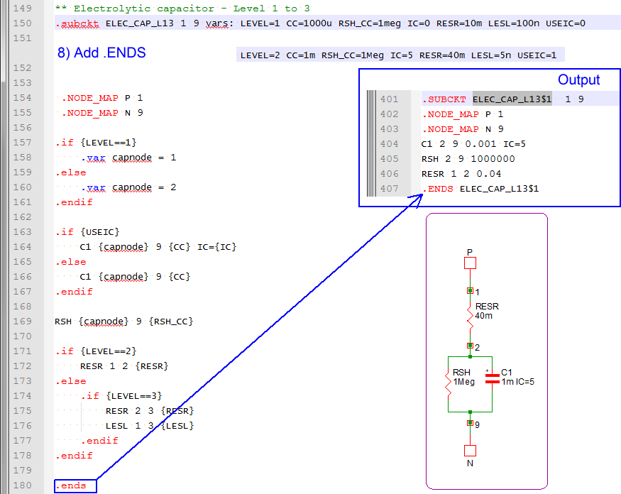
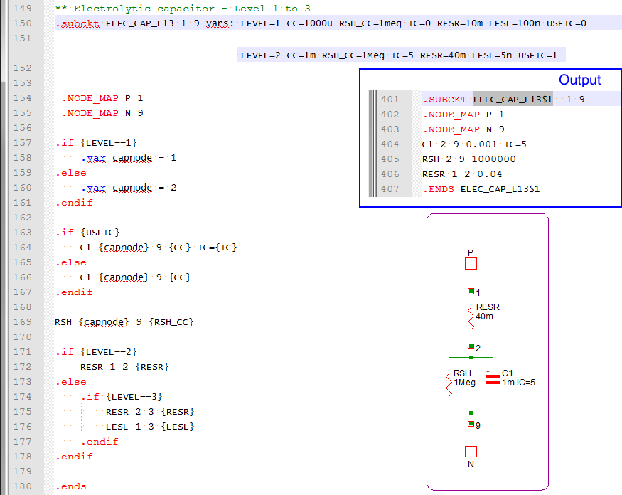
The capacitor C1 is a Level 2 capacitor - meaning the capacitor is a network of an ideal capacitor, a shunt resistance, and a series resistance. The parameters passed into the subcircuit are used to both determine the schematic configuration of the subcircuit capacitor, as well as to set the values for each circuit element. Note: Extra parameters can be passed into the subcircuit at the netlist stage. In this case, the LESL parameter is not used by the subcircuit after the preprocessor has been run, because there is logic contained in the model that keys off the value of the LEVEL parameter. This logic determined that the equivalent series inductor was not to be included in the final simulation deck file.
The subcircuit definition for the capacitor C2 immediately precedes the subcircuit for C1. Note the subcircuit contains the same devices, connected to the same subcircuit net numbers, but the circuit element values are different.
Subcircuit Creation Slideshow
The following slideshow shows the netlist preprocessor as it steps through the model definition from the library, and generates the actual subcircuit. Note that the netlist preprocessor eliminates any blank lines and all comment lines which begin with an asterisk.
- You can pause the slideshow by moving the mouse cursor over the images.
- To go forward or back one slide, click the arrow links that appear when you mouse over the slideshow. You can also use the left and right arrow keys to go forward or to go back one slide.
- You can jump to a particular slide by clicking one of the gray squares at the bottom on the image. The current slide is indicated by the white square.
Conclusions and Key Points to Remember
- The netlist preprocessor copies subcircuit definitions from the global library to the deck file, then evaluates the parameters and conditional branches defined with the .IF and .ELSE statements.
- Parameters are passed into the subcircuits on the netlist instantiation line. The instantiation line is created by the netlister based on the symbol's template property.
- Parameters can be used to dynamically create the resulting subcircuit definitions.
- Each netlist instantiation line calls a unique subcircuit which is created by the netlist preprocessor.
- The subcircuit interface is generic, and defines:
- The node number that each pin of this subcircuit is connected to
- Parameters whose values are passed into the subcircuit